
Lateral protecting mechanism and child restraint system therewith

a technology of lateral protection and child restraint, which is applied in the field of child products, can solve the problems of occupying more space, affecting the functioning of foldable lateral protection devices, and affecting the safety of passengers sitting nearby, so as to reduce the lateral impact force, save space, and simplify the operation

Active Publication Date: 2021-03-02
WONDERLAND SWITZERLAND AG
View PDF20 Cites 2 Cited by
  • Summary
  • Abstract
  • Description
  • Claims
  • Application Information

AI Technical Summary

Benefits of technology

The present invention provides a lateral protecting mechanism for a child carrier that can automatically unfold and fold as needed. The mechanism includes a positioning protrusion and a positioning rib that work together to secure the protecting block in place, preventing it from leaving the folded position. This mechanism simplifies the process of unfolding the protecting block in case of an emergency and prevents users from forgetting to unfold it. The operating component can be easily saved space when folded and can still be operated to secure the protecting block in place. The locking component slides to the locking position without interfering with the unfolded protecting block, making it more convenient for users.

Problems solved by technology

However, such configuration not only occupies more space but also interferes with other passengers sitting nearby.
However, sometimes, a user or a caregiver may forget to unfold a foldable lateral protecting device before travelling, so that the foldable lateral protecting device cannot work properly when an emergency brake or a collision of a vehicle occurs.
Besides, two foldable lateral protecting devices at two lateral sides are configured to be maintained in unfolded states together, and a user or a caregiver cannot selectively fold one of the two foldable lateral protecting devices to a folded state according to practical demands after the two foldable lateral protecting devices are operated to be in the unfolded states.

Method used


Image

  • Lateral protecting mechanism and child restraint system therewith
  • Lateral protecting mechanism and child restraint system therewith
  • Lateral protecting mechanism and child restraint system therewith

Examples


Embodiment Construction

[0040]In the following detailed description of the preferred embodiments, reference is made to the accompanying drawings which form a part hereof, and in which is shown by way of illustration specific embodiments in which the invention may be practiced. In this regard, directional terminology, such as “top,”“bottom,”“front,”“back,” etc., is used with reference to the orientation of the Figure(s) being described. The components of the present invention can be positioned in a number of different orientations. As such, the directional terminology is used for purposes of illustration and is in no way limiting. Accordingly, the drawings and descriptions will be regarded as illustrative in nature and not as restrictive.

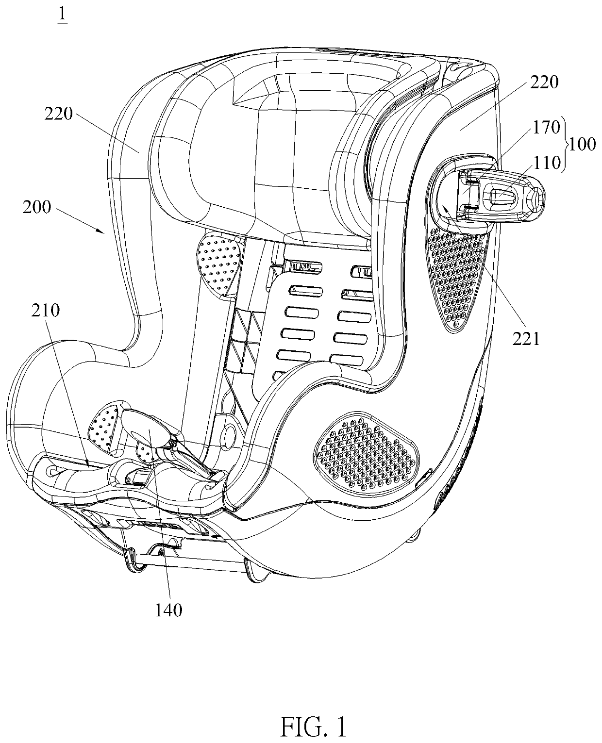
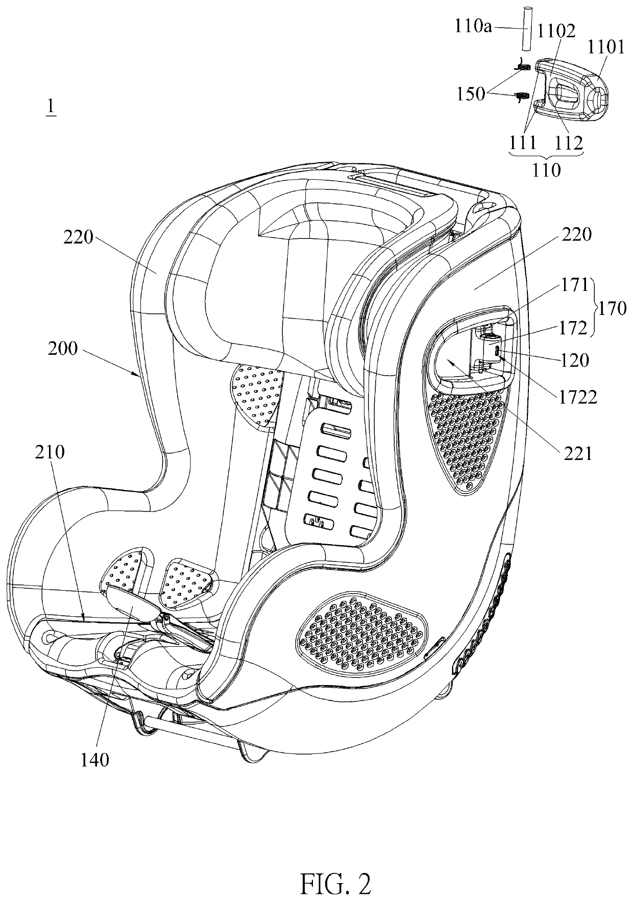
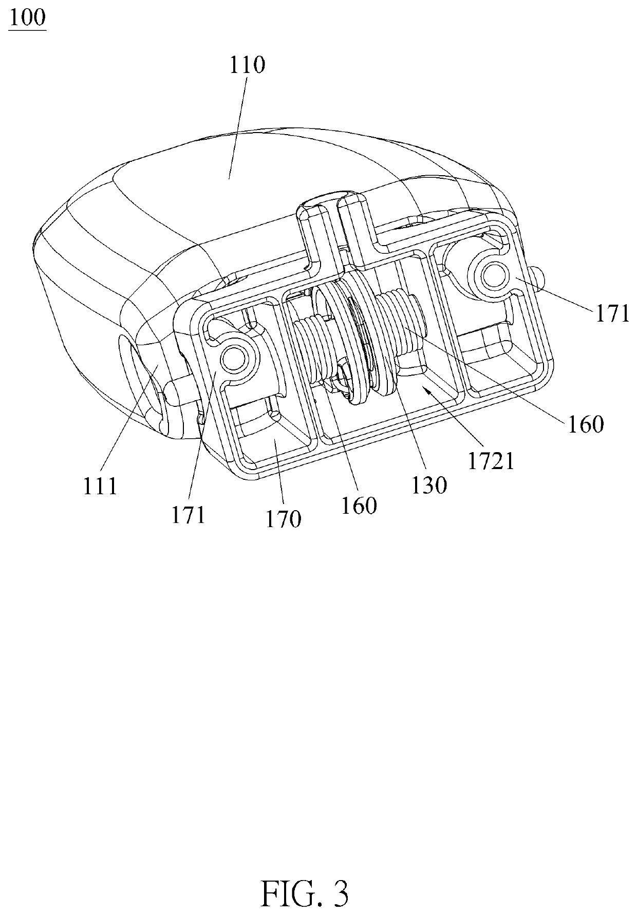
[0041]Please refer to FIG. 1, FIG. 2, FIG. 10 and FIG. 11. FIG. 1 is a schematic diagram of a child restraint system 1 according to an embodiment of the present invention. FIG. 2 is a diagram of the child restraint system 1 as a protecting block 110 is detached from a child...


PUM


Abstract

A lateral protecting mechanism includes a protecting block, a locking component, a driving component and an operating component. The protecting block is pivotally disposed on a lateral portion of a child carrier. The locking component is slidably disposed on the lateral portion of the child carrier. The protecting block is allowed to pivotally switch between an unfolded position and a folded position when the locking component is located at a releasing position. The protecting block at the folded position is restrained from leaving from the folded position when the locking component is located at a locking position. The driving component is for driving the locking component to slidably switch between the locking position and the releasing position. The operating component is coupled to the driving component for driving the driving component to drive the locking component to slide to the locking position when the operating component is operated.

Description

BACKGROUND OF THE INVENTION1. Field of the Invention[0001]The present invention relates to a child product, and more particularly, to a lateral protecting mechanism and a child restraint system therewith.2. Description of the Prior Art[0002]A child safety seat, a kind of a child restraint, is an apparatus installed on a seat of a vehicle and provided with a restraint device, such as a harness device, for securing a child sitting therein when traveling. When an emergency brake or a collision of the vehicle occurs, the child restraint can reduce impact forces acting on the child and restrain the child's body movement by the restraint device for preventing injury or death of the child for ensuring sitting safety of the child.[0003]Currently, in order to reduce lateral impact forces, child restraints are provided with lateral protecting devices at lateral sides. However, a conventional lateral protecting device is open and usually fixedly disposed on a lateral portion of a child restrai...

Claims


Application Information

Patent Timeline
Patent Type & Authority Patents(United States)
IPC IPC(8): A47C1/00A47D1/10B60N2/28
CPCB60N2/2872B60N2/2812B60N2/2884B60N2/4235
Inventor CUI, ZONG-WANG
Owner WONDERLAND SWITZERLAND AG
Learn More