Touch panel-equipped display device

a display device and touch panel technology, applied in the field of touch panel-equipped display devices, can solve the problems of vibration non-uniformity, vibration change in hardness (elasticity) of rubber bush with temperature change, and the inability to transmit vibration efficiently, so as to suppress the transmission of vibration. the effect of efficient transmission of vibration

Active Publication Date: 2021-03-02
STANLEY ELECTRIC CO LTD
View PDF4 Cites 0 Cited by
  • Summary
  • Abstract
  • Description
  • Claims
  • Application Information

AI Technical Summary

Benefits of technology

[0007]An aspect of the present invention provides a touch panel-equipped display device capable of efficiently transmitting vibration from a vibration element according to an operation of a touch panel and suppressing vibration transmitted from a front-side case to a back-side case.
[0024]As described above, according to the aspect of the present invention, it is possible to provide a touch panel-equipped display device capable of efficiently transmitting vibrations from a vibration element according to an operation on a touch panel and suppressing vibration transmitted from a front-side case to a back-side case.

Problems solved by technology

Incidentally, in the above-mentioned touch panel-equipped display device, there are restrictions on the disposition of a vibration element, and vibrations from the vibration element may not be able to be transmitted efficiently, resulting in vibration non-uniformity.
However, when such rubber bushes are used, the hardness (elasticity) of a rubber bush changes with respect to temperature change.
For this reason, differences may occur in vibrations transmitted from the vibration element, vibrations from the vibration element may not be able to be efficiently transmitted, or the control board or the like may be adversely influenced by vibrations transmitted from the front-side case to the back-side case.

Method used


Image

  • Touch panel-equipped display device
  • Touch panel-equipped display device
  • Touch panel-equipped display device

Examples


Embodiment Construction

[0031]Hereinafter, an embodiment of the present invention will be described in detail with reference to the accompanying drawings.

[0032]Further, in the drawings used in the following description, in order to make components easier to see, dimensional scales may be different depending on the components, and dimensional ratios or the like in each component may not always be the same as actual ones.

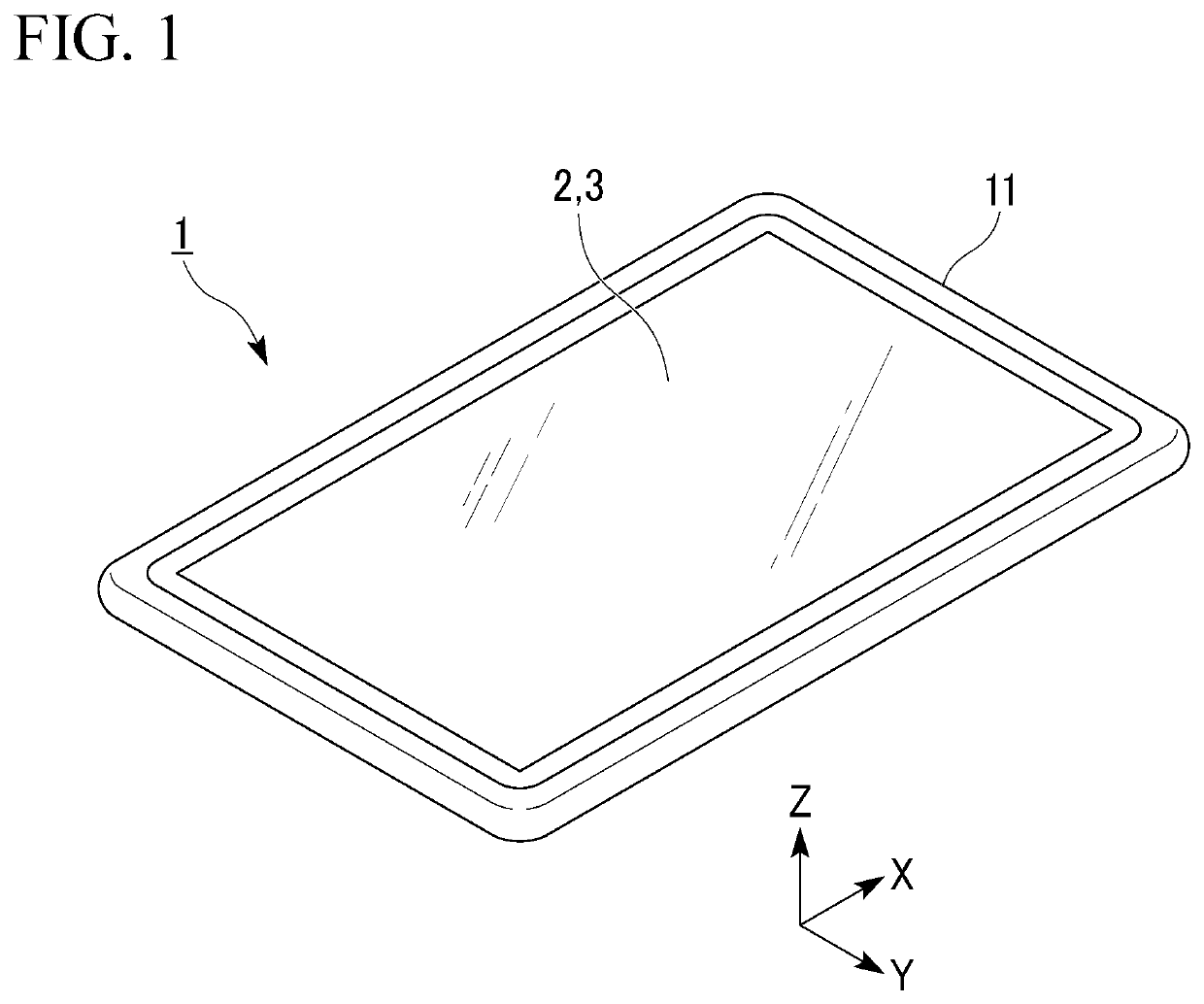
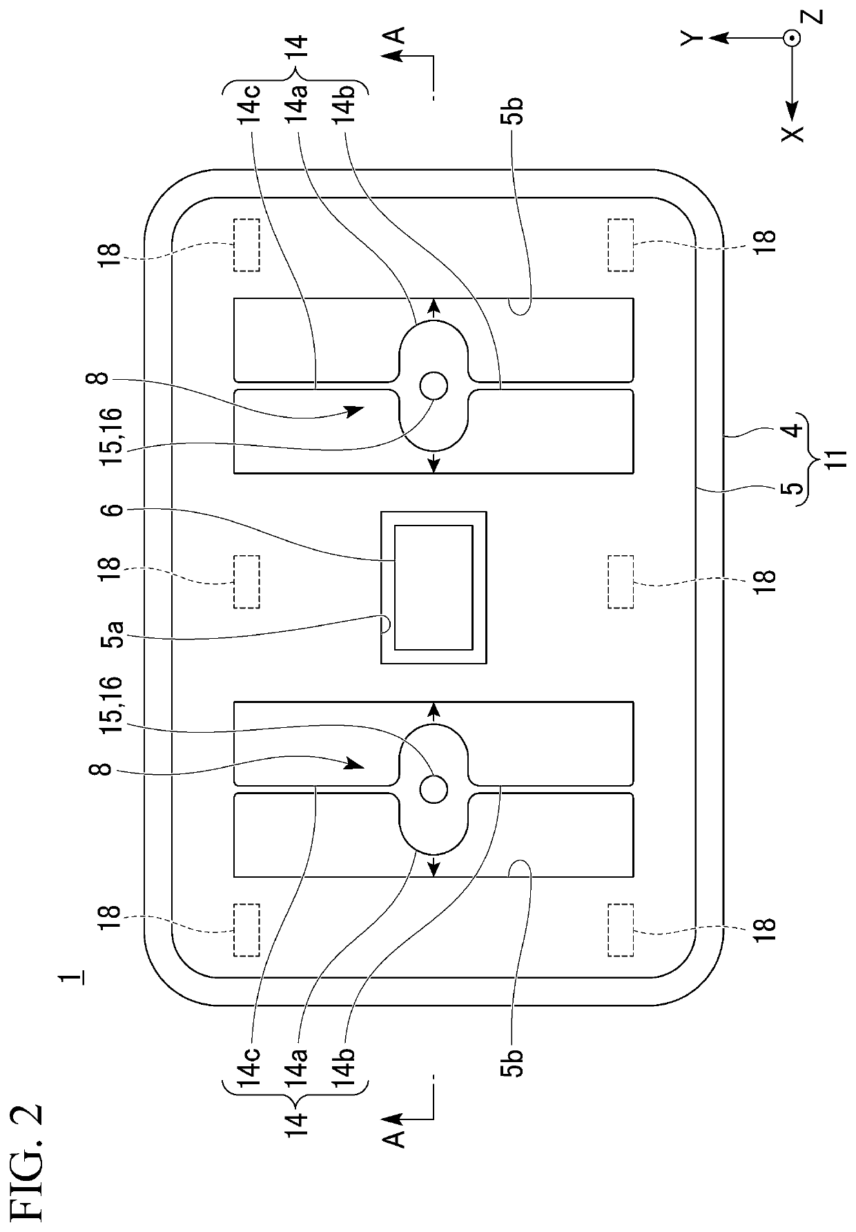
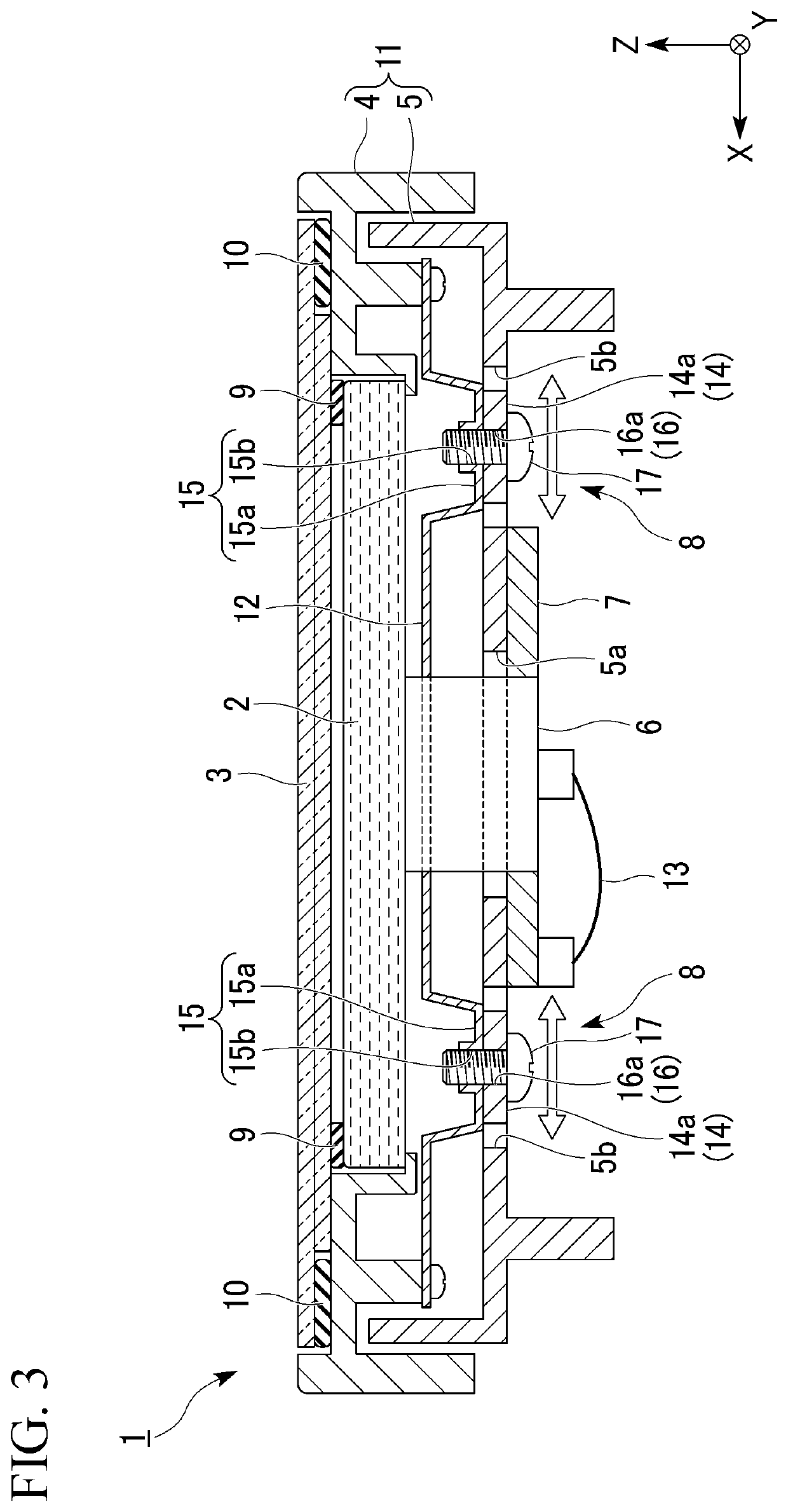
[0033]As an embodiment of the present invention, for example, a touch panel-equipped display device 1 shown in FIG. 1 to FIG. 4 will be described.

[0034]Further, FIG. 1 is a perspective view showing an appearance of the touch panel-equipped display device 1. FIG. 2 is a transparent plan view showing a configuration of the touch panel-equipped display device 1. FIG. 3 is a cross-sectional view of the touch panel-equipped display device 1 taken along line segment A-A shown in FIG. 2. FIG. 4 is a perspective view showing a configuration of an elastic displacement section 14 provided in the touch...


PUM


Abstract

A touch panel-equipped display device includes a front-side case that accommodates a display panel and a touch panel overlap each other, a support plate fixed at a side opposite with respect to a display surface of the front-side case, a back-side case disposed at a side opposite of the display panel with respect to the support plate, a vibration element fixed between the back-side case and the support plate and that vibrates the front-side case and the support plate in an in-plane direction of the display panel according to an operation on the touch panel, and a damper mechanism that supports the front-side case or the support plate so that the front-side case or the support plate is capable of being freely vibrated in the in-plane direction of the touch panel, wherein the damper mechanism has an elastic displacement section elastically displaced in the in-plane direction of the back-side case.

Description

CROSS-REFERENCE TO RELATED APPLICATION[0001]Priority is claimed on Japanese Patent Application No. 2018-241193, filed Dec. 25, 2018, the content of which is incorporated herein by reference.BACKGROUNDField of the Invention[0002]The present invention relates to a touch panel-equipped display device.Description of Related Art[0003]In the related art, there is a touch panel-equipped display device including a display panel and a touch panel, and capable of enabling various inputs by the touch panel being operated according to an image displayed on the display panel (for example, see Japanese Unexamined Patent Application, First Publication No. 2008-287402). In addition, among the touch panel-equipped display device in the related art, devices that include a vibration element configured to generate vibrations (according to a sense of touch) according to operations of the touch panel are known.SUMMARY OF THE INVENTION[0004]Incidentally, in the above-mentioned touch panel-equipped display...

Claims


Application Information

Patent Timeline
Patent Type & Authority Patents(United States)
IPC IPC(8): G06F3/041G06F3/01
CPCG06F3/0412G06F3/016G06F1/1626G06F1/1643
Inventor TAKAHASHI, KAZUYA
Owner STANLEY ELECTRIC CO LTD
Why Eureka
Try Eureka