
Apparatus and method for improved phase separation in immiscible fluids

a technology of immiscible fluids and apparatus, which is applied in the direction of water treatment parameter control, food waste water treatment, water/sludge/sewage treatment, etc., can solve the problems of affecting the overall operation of the centrifuge machine, the centrifuge machine needs too much energy, and the overall cost is too high

Active Publication Date: 2021-03-09
GHADYANI MOHAMMAD
View PDF2 Cites 0 Cited by
  • Summary
  • Abstract
  • Description
  • Claims
  • Application Information

AI Technical Summary

Benefits of technology

[0012]The delay element is configured to calculate error time. The opening of the second outlet and the closing of the first outlet is delayed for the calculated error time, to ensure complete evacuation of fluid of first phase and to increase accuracy. After completion of the error time, the second outlet is opened for evacuation of fluid of second phase.

Problems solved by technology

Additionally, oil slicks are caused by excavation and extraction, activities in oil terminals, broken pipe in pipeline transportation, broken ships and oil lorries.
The other industrial way is to use a centrifuge machine which separates the phases in high accuracy but the centrifuge machine needs too much energy and is generally too expensive.
None of them is comprehensive and all of them have some deficiencies.
Because of the of lack of desirable efficiency in industrial scale or high cost or difficulty in application, these methods are generally not used, and this causes irreparable damages to the environment.

Method used


Image

  • Apparatus and method for improved phase separation in immiscible fluids
  • Apparatus and method for improved phase separation in immiscible fluids
  • Apparatus and method for improved phase separation in immiscible fluids

Examples


Embodiment Construction

9]The present invention generally relates to a decantation of a multi-phase fluid mixture and more particularly relates to an apparatus and method for providing improved automatic decantation of multi-phase chemical fluid.

[0040]A description of embodiments of the present invention will now be given with reference to the figures. It is expected that the present invention may be embodied in other specific forms without departing from its spirit or essential characteristics. The described embodiments are to be considered in all respects only as illustrative and not restrictive. The scope of the invention is, therefore, indicated by the appended claims rather than by the foregoing description. All changes that come within the meaning and range of equivalency of the claims are to be embraced within their scope.

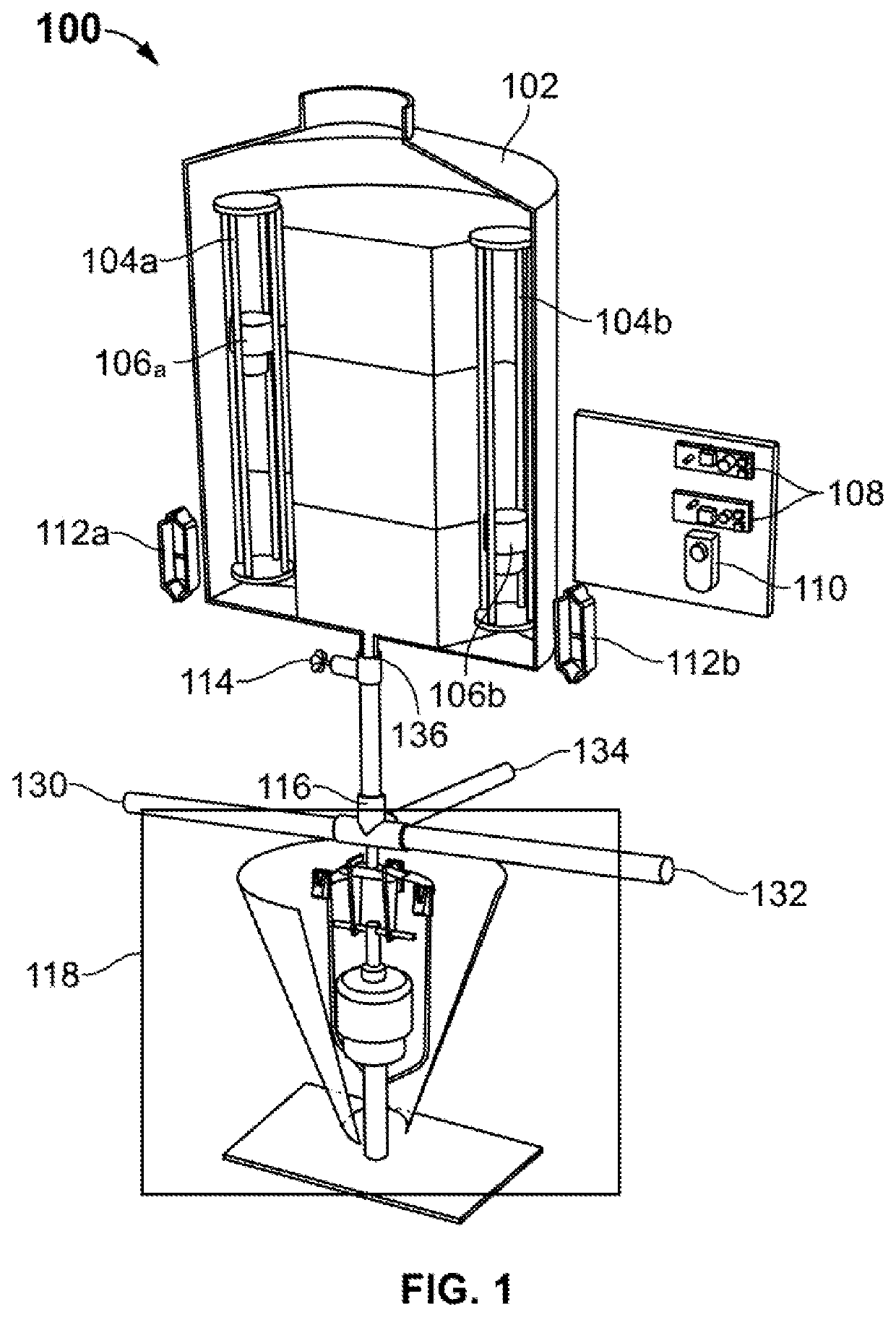
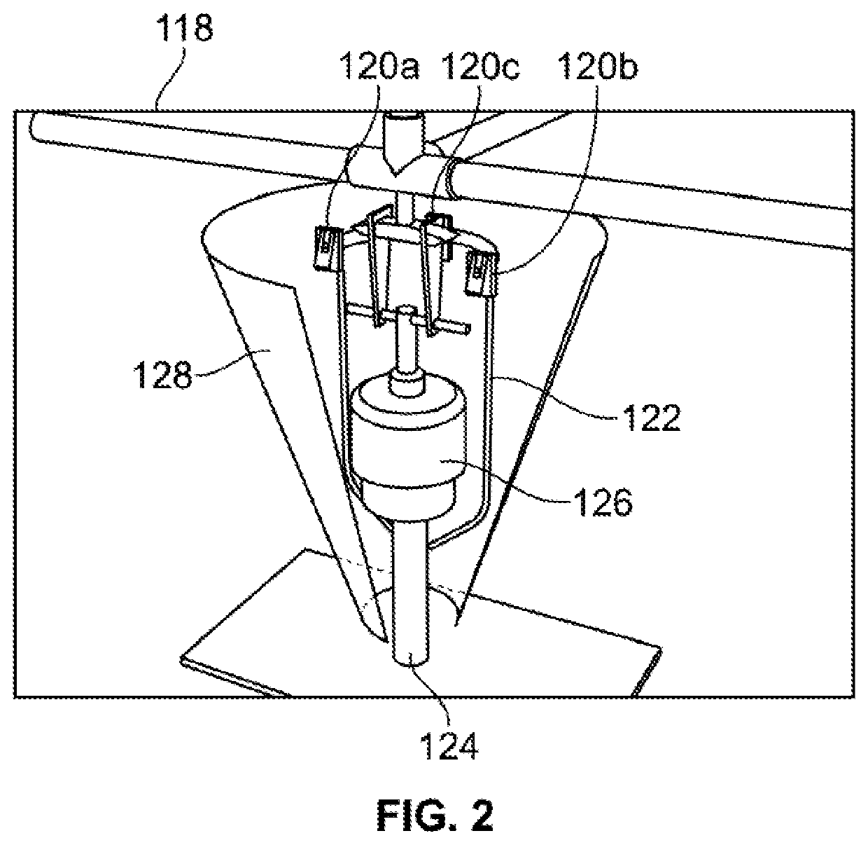
[0041]Referring to FIG. 1, an apparatus 100 for automated decantation of three-phase fluids is illustrated, according to an embodiment of the present invention. The apparatus 100 c...


PUM

PropertyMeasurementUnit
densityaaaaaaaaaa
timeaaaaaaaaaa
densitiesaaaaaaaaaa

Abstract

An apparatus and method for automated decantation of multi-phase fluid is disclosed. The apparatus for two phase fluid comprises a fluid line assembly, a floating marker, a sensor, an actuator assembly and a control board. The fluid line is attached to a reservoir containing the multi-phase fluid, comprising an inlet and two outlets. A three-way valve is disposed between the inlet and the two outlets. The floating marker is disposed within a cylindrical frame mounted within the reservoir. The selective density of the float marker is selected between the density values of two fluids in the multi-phase fluid. The float-marker floats between the two fluid phases due to the density of the float marker and fluid. The actuator assembly, configured to operate inlets and outlets of the fluid line. The number of outlets, sensor, and floating marker increases with the number of phases of fluid.

Description

BACKGROUND OF THE INVENTION[0001]Producing immiscible waste water such as water and oil is inevitable in different industries. Particularly, industries related to petroleum such as refineries' spent caustic, petroleum refining and fabricating and petrochemical products produces multiphase waste water. Some industries such as steel industry and plotting industry, glass industry, and food industry produces two-phase waste water because of utilization of oil. Additionally, oil slicks are caused by excavation and extraction, activities in oil terminals, broken pipe in pipeline transportation, broken ships and oil lorries. Hence, to reduce the damage caused to the economy and environment by the immiscible waste, a comprehensive method is needed to separate and return water / oil to the respective product line.[0002]Generally, a separation funnel is used in liquid-liquid extractions to separate the components of a mixture into two or more phases on the basis of densities of the liquid. To u...

Claims


Application Information

Patent Timeline
Patent Type & Authority Patents(United States)
IPC IPC(8): B01D17/12B01D17/02C02F1/40C02F1/00C02F103/32C02F103/36C02F103/16C02F103/12
CPCB01D17/12B01D17/0214C02F1/008C02F1/40C02F2103/12C02F2103/16C02F2103/32C02F2103/365C02F2209/01C02F2209/40C02F2209/42C02F2209/006C02F2209/44
Inventor GHADYANI, MOHAMMAD
Owner GHADYANI MOHAMMAD
Learn More