Detachable power cord structure for portable hair curler

a portable, power cord technology, applied in the direction of flexible/turnable line connectors, curling-tongs, coupling device connections, etc., can solve the problems of inability to be easily carried and arranged in places, and achieve the effect of effective ensuring the service life of tail wires and high versatility

Active Publication Date: 2021-03-09
DONGGUAN LISI INTELLIGENT TECH CO LTD
View PDF13 Cites 2 Cited by
  • Summary
  • Abstract
  • Description
  • Claims
  • Application Information

AI Technical Summary

Benefits of technology

[0005]In order to solve the above-mentioned defects of the related art, the technical solution provided by the present invention is: a detachable power cord structure for a portable hair curler, including a device tail sleeve and a tail wire, wherein the device sleeve is provided with an elastic engaging assembly, the tail wire is inserted into the device tail sleeve and is engaged with the elastic engaging assembly. When the tail wire is engaged with the elastic engaging assembly, it can turn on the circuit and can be rotated freely.
[0015]Compared with the existing art, the present invention has the advantages that the power connector structure adopted by the present invention can be rotated through the insertion of the device tail sleeve and the tail wire, and the elastic engaging assembly is arranged in the device tail sleeve. The tail wire is inserted into the device tail sleeve and is engaged with the elastic engaging assembly. When the tail wire is engaged into the elastic engaging assembly, it can turn on the circuit and rotated freely. When the tail wire is electrically connected, it can be rotated freely without bending or curving during use, thereby effectively ensuring the service life of the tail wire, and to some extent, it has a protective effect on the power cord. Moreover, the power connector of the product can be adapted to the power docking of various hairdressing appliances, can be replaced at will, and has high versatility.

Problems solved by technology

For power connectors that cannot be detached, they cannot be easily carried and arranged in places.

Method used


Image

  • Detachable power cord structure for portable hair curler
  • Detachable power cord structure for portable hair curler

Examples


Embodiment Construction

[0020]The present invention will be further described below based on the drawings and specific embodiments, but embodiments of the present invention are not limited thereto.

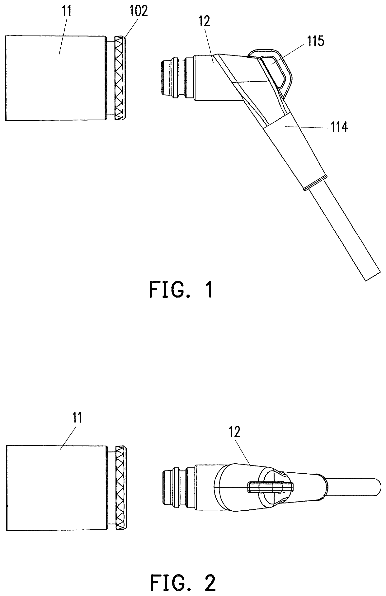
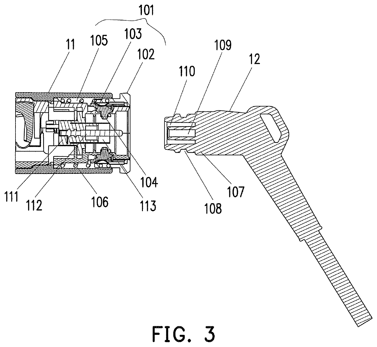
[0021]As shown in FIG. 1, FIG. 2 and FIG. 3, a detachable power cord structure for a portable hair curler includes a device tail sleeve 11 and a tail wire 12. An elastic engaging assembly 101 is arranged in the device tail sleeve 11. The tail wire 12 is inserted into the device tail sleeve 11 and is engaged with the elastic engaging assembly 101. When the tail wire 12 is engaged into the elastic engaging assembly 101, it can turn on the circuit and can be rotated freely.

[0022]Preferably, the elastic engaging assembly 101 includes a tail spring ring 102. One end of the tail spring ring 102 extending into the device tail sleeve 11 is provided with a buckle 103. The inside of the buckle 103 is provided with a protrusion 104, and a spring groove 105 is disposed on the inner side wall of the device tail sleeve 11. A t...


PUM


Abstract

The present invention discloses a detachable power cord structure for a portable hair curler, including a device tail sleeve and a tail wire. An elastic engaging assembly is arranged in the device tail sleeve, the tail wire is inserted into the device tail sleeve, and is engaged with the elastic engaging assembly. When the tail wire is engaged into the elastic engaging assembly, it can turn on the circuit and can be rotated freely. The power connector structure adopted by the present invention can be rotated through insertion of the device tail sleeve and the tail wire, and the elastic engaging assembly is arranged in the device tail sleeve. The tail wire can be rotated freely while the electrical connection is realized, and the tail wire is not bent or curved during use, thereby effectively ensuring the service life of the tail wire.

Description

CROSS-REFERENCE TO RELATED APPLICATION[0001]This application claims the priority benefit of China application serial no. 201910828380.0, filed on Sep. 3, 2019. The entirety of the above-mentioned patent application is hereby incorporated by reference herein and made a part of this specification.BACKGROUNDTechnical Field[0002]The present invention relates to a hairdressing product, in particular to a detachable power cord structure for a portable hair curler.Description of Related Art[0003]At present, there are many kinds of electrical appliances for hairdressing, which have different functions according to different hairdressing effects, such as: hair curler, hair-straightening comb, hair-curling comb, hair iron, hair dryer, electric hair dryer comb or hair straightener, etc. The existing power connector parts of these appliances are generally connected through a fixed power cord slot on the casing. For power connectors that cannot be detached, they cannot be easily carried and arra...

Claims


Application Information

Patent Timeline
Patent Type & Authority Patents(United States)
IPC IPC(8): H01R13/187H01R13/22H01R13/10A45D6/00
CPCH01R13/187H01R13/10H01R13/22A45D2006/005H01R31/06H01R35/00A45D2/00A45D20/10A45D20/12H01R39/64H01R24/38H01R24/20H01R24/28H01R13/6277H01R13/6315A45D1/20H01R13/639A45D2001/002
Inventor PENG, JINHU
Owner DONGGUAN LISI INTELLIGENT TECH CO LTD
Why Eureka
Try Eureka