System and methods for adjusting variable variable geometry, height, weight distribution dynamics in orthotic devices and equipment

a technology of variable geometry and dynamic flex adjustment, applied in the field of orthotic shoe inserts, can solve the problems of inability to change the characteristics, subtle changes in the stiffness or flexibility characteristics of sporting or fitness equipment that are not available between different pieces of sporting equipment, and inability to achieve significant changes in the stiffness or flexibility characteristics of sporting or fitness equipment, so as to enhance the imbalance of the lower extremity or foot, enhance athletic performance, and maintain consistent flex adjustment

Active Publication Date: 2021-03-30
ALLIANCE DESIGN & DEVMENT GROUP
View PDF12 Cites 2 Cited by
  • Summary
  • Abstract
  • Description
  • Claims
  • Application Information

AI Technical Summary

Benefits of technology

[0044]An advantage of the present invention is the ability to provide constant and consistent flex adjustment. This advantage arises from the adjustment being locked in at the ends of the shaft and, depending upon the application, at one or more additional locations through the length of the shaft.
[0045]A resilient rod acting alone is also embodied to create resistance that incorporates adjustable flex or resistance by means of hand position and/or specific rotation for means of exercise employing progressive dynamic resistance, which relates to the advantages in exercise of varying degree weight and resistance through a particular cycle.
[0046]The present invention embodies flexible materials and devices that form geometries that conformally map or dynamically contour to foot structures in proportion (i.e., ergonomically conform, deform, and/or change shape) to a mechanical setting of a Variable Resistance Beam (VRB) resistance or suspension range settings in balanced proportion to downward foot loading.
[0047]In accordance with the principles of the

Problems solved by technology

In many cases, the availability is limited due to cost and over all impracticability.
Additionally, subtle but important changes in the stiffness or flexibility characteristics of sporting or fitness equipment may not be available between different pieces of sporting equipment, because the characteristics may be set by the manufacturer from the choice of materials, design, etc., and to change the characteristics would be impossible, as such customization isn't offered to the user.
Further, the user must have the different pieces of sporting equipment nearby during play or they are essentially in practice unavailable to the user.
Thus, it can be seen how the lack of adjustability in stiffness and flexibility may adversely affect optimum performance of a device, apparatus, and equipment.
Turning to additional types of devices, apparatus and equipment, it can be seen how the lack of a practical means of adjustability in stiffness and flexibility may adversely affect performance.
Yet the degree of adjustability of braces is limited, and, in most cases, fixed.
This often involves the continued and time consuming adjustment of equipment through an exercise cycle and makes changes impractical at best, and at the least a hassle.
When the user changes resistance/weight or machine during an exercise set, it is time consuming and interrupts the user's conditioning.
If the sole is too stiff, however, the toe-heel flex of the foot is hindered.
However, this process is performed by the manufacturer and is beyond the ability of the average user.
Varying the stiffness or flexibility of the golf club is not possible, unless the golfer brings another set of clubs.
Nevertheless, it is impractical to carry a large number of golf clubs onto the course, wherein each club having a slight nuance of difference in flexibility and stiffness than another.
Younger players may require more flex in the hockey stick due to lack of strength; such flex m

Method used


Image

  • System and methods for adjusting variable variable geometry, height, weight distribution dynamics in orthotic devices and equipment
  • System and methods for adjusting variable variable geometry, height, weight distribution dynamics in orthotic devices and equipment
  • System and methods for adjusting variable variable geometry, height, weight distribution dynamics in orthotic devices and equipment

Examples


Embodiment Construction

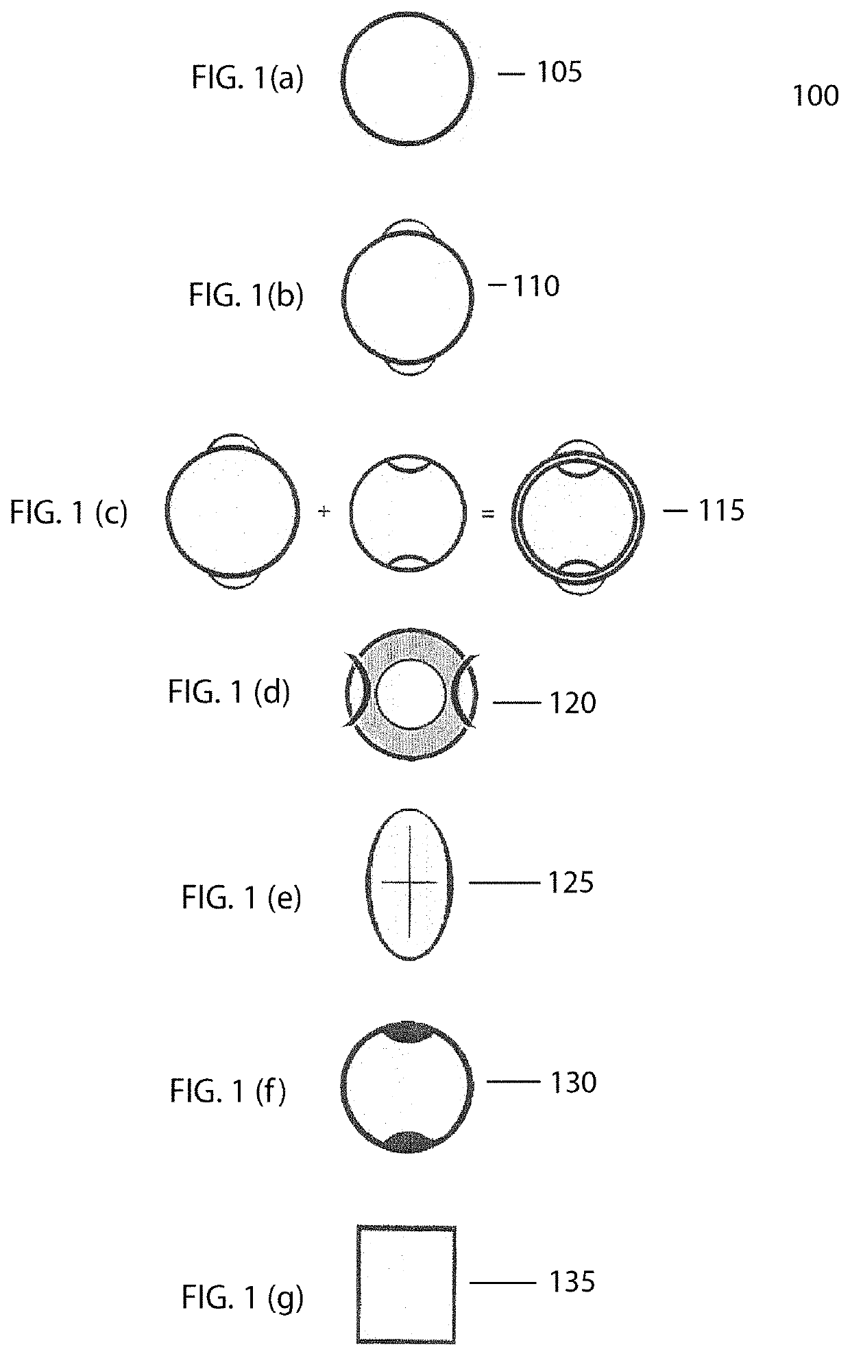
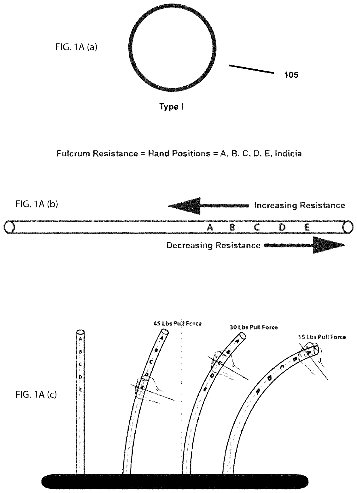
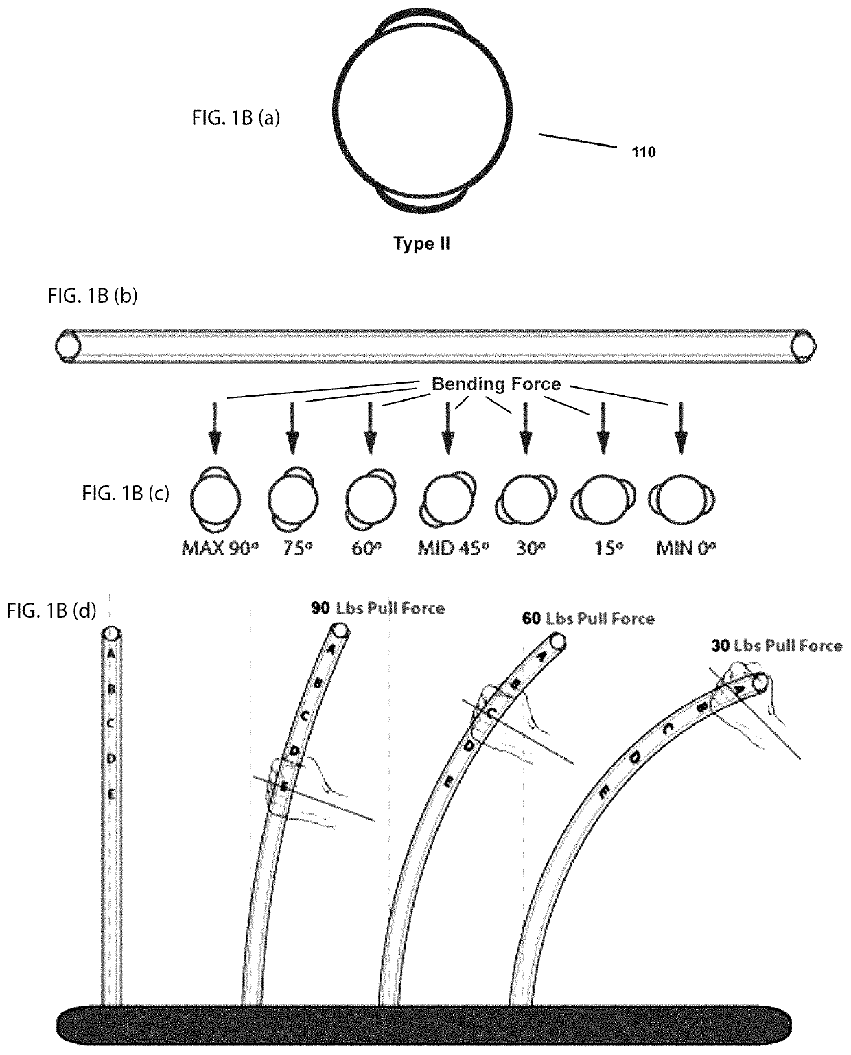
[0106]The object of the present invention is to adjust the flexibility and thereby the resistance of a rod by hand positioning in relationship to the fulcrum of rod; or by bending a rod and spine within the shaft; or by bending a single solid rod; or both the bending of an outer beam and an inner beam in another example. This affects the longitudinal flex and the kick or hinge point of flexure where maximum flexure bending forces arise, depending on the hand position or anchor point in relationship to the fulcrum.

[0107]A shaft includes any tube-like structure by itself, attached to the outside of another surface or incorporated within a structure. Examples of a tube-like shaft by itself include hockey sticks, golf clubs, lacrosse sticks, pole vaulting poles, fishing rods, sailboard / sailboard masts, canoe / kayak paddles or oars, baseball bats, archery bows, tennis racquets and exercise machine tensioning rods. Examples of products to which a tube-like shaft might be attached externall...


PUM

PropertyMeasurementUnit
Angleaaaaaaaaaa
Angleaaaaaaaaaa
Fractionaaaaaaaaaa

Abstract

An active suspension orthotic support system is disclosed. The suspension orthotic support system comprises at least one variable resistance beam extending from a heel section to a mid-arch section of the footwear, wherein rotation of the variable resistance beam from a first position to a second position causes a resistance provided by the variable resistance beam to vary between a minimum resistance to a maximum resistance.

Description

CLAIM OF PRIORITY[0001]This application claims, pursuant to 35 USC 119, priority to and the benefit of the earlier filing date of provisional patent application Ser. No. 62 / 620,951, filed on Jan. 23, 2018 and further claims, under 35 USC 120, as a Continuation-in-Part application, priority to that patent application filed on Feb. 26, 2017 and afforded Ser. No. 15 / 425,772 (U.S. Pat. No. 10,188,173), which claimed pursuant to 35 USC 120, as a Continuation application, priority to that patent application, filed on Nov. 17, 2014 and afforded Ser. No. 14 / 543,870 (U.S. Pat. No. 9,603,416), which claimed, pursuant to 35 USC 119, priority to and the benefit of the earlier filing date of that provisional patent application filed on Nov. 18, 2013 and afforded Ser. No. 61 / 905,688 and further claimed pursuant to 35 USC 120, as a continuation in part, priority to that patent application filed on Sep. 18, 2012 and afforded Ser. No. 13 / 622,331, (now Abandoned) which claimed the benefit of the earl...

Claims


Application Information

Patent Timeline
IPC IPC(8): A43B7/24A43B3/00A43B7/14A63B59/50A63B21/00A63B59/20A63B59/70A63B53/10A63B49/02A63B23/12A63B22/06A63B22/02A63B22/00A63B21/04A63B21/02A61F5/01A63C5/07A01K87/00A01L7/06A43B17/04A43B17/14A63B60/50A63B23/035A63B24/00A63B71/06A01D7/00A63B5/06A43B3/24A63C5/04A43B17/02A61B5/00A63B102/18A63B102/24A63B71/02A63B102/22A63B102/02A63B21/16A63B6/02A63B69/36A63B69/18A63B69/16A63B69/00A63B23/04A63B69/06A63B60/42A63B22/04
CPCA43B7/24A01D7/00A01K87/00A01L7/06A43B3/0005A43B3/0015A43B3/246A43B7/141A43B7/142A43B7/143A43B7/1445A43B7/1465A43B17/02A43B17/04A43B17/14A61F5/0102A61F5/0111A61F5/0123A63B5/06A63B21/0004A63B21/00069A63B21/00072A63B21/026A63B21/0442A63B21/4023A63B21/4029A63B21/4035A63B21/4037A63B21/4043A63B22/0056A63B22/02A63B22/0605A63B22/0664A63B23/03533A63B23/1209A63B24/0062A63B49/02A63B53/10A63B59/20A63B59/50A63B59/70A63B60/50A63B71/0622A63C5/04A63C5/07A61B5/4528A61B5/6812A61B2505/09A61B2562/0219A61B2562/0261A63B6/02A63B21/16A63B21/169A63B22/0012A63B22/04A63B23/03508A63B23/03525A63B23/03541A63B23/0405A63B60/42A63B69/0093A63B69/06A63B69/16A63B69/18A63B69/36A63B71/023A63B2071/027A63B2071/0694A63B2102/02A63B2102/18A63B2102/22A63B2102/24A63B2209/02A63B2210/50A63B2220/24A63B2220/40A63B2220/52A63B2220/53A63B2220/56A63B2225/09A63B2225/093A63B2225/20A63B2225/50A63B2225/54A63C2203/20A01D7/06A43B13/181A61B5/6802A63C5/075A63B2244/19A63B2102/32A63B2209/14A43B7/1464A43B3/44A43B7/1466A43B13/141A43B3/34A43B3/38
Inventor TARLTON, PETER B.
Owner ALLIANCE DESIGN & DEVMENT GROUP
Why Eureka
Try Eureka