Percussive therapy device with active control

a percussive therapy and active control technology, applied in the field of massage devices, can solve the problems of superficial massages that are not effective, and ineffective use of percussive massage devices, etc., to achieve precise and personalized treatment, reduce sound from vibration, and improve the effect of treatment

Active Publication Date: 2021-03-30
THERABODY INC
View PDF71 Cites 39 Cited by
  • Summary
  • Abstract
  • Description
  • Claims
  • Application Information

AI Technical Summary

Benefits of technology

[0025]In accordance with another aspect of the present invention there is provided a massage device that includes a housing, an electrical input, a motor, a switch in electrical communication with the electrical input and the motor and configured to selectively provide power from the electrical input to the motor, an actuated output operatively connected to the motor and configured to reciprocate in response to activation of the motor, and a treatment structure operatively connected to a distal end of the actuated output. The actuated output is configured to reciprocate the treatment structure at a frequency of between about 15 Hz and about 100 Hz, and at an amplitude of between about 0.15 and about 1.0 inches. The combination of amplitude and frequency provides efficient reciprocation of the treatment structure such that the treatment structure provides therapeutically beneficial treatment to a targeted muscle of a user.
[0049]The device includes a push rod or shaft that is connected directly to the motor by a pin. In a preferred embodiment, the push rod is L-shaped or includes an arc shape. Preferably, the point where the push rod is connected to the pin is offset from reciprocating path that the distal end 40 of the push rod (and the massage attachment) travel. This capability is provided by the arc or L-shape. It should be appreciated that the push rod is designed such that it can transmit the force diagonally instead of vertically so the motor can be located at or near the middle of the device, otherwise a protrusion would be necessary to keep the shaft in the center with the motor offset therefrom (and positioned in the protrusion). The arc also allows the push rod to have a close clearance with the motor and allows the outer housing to be smaller than similar prior art devices, therefore making the device lower profile. Preferably two bearings are included at the proximal end of the push rod where it connects to the motor to counteract the diagonal forces and preventing the push rod for moving and touching the motor.
[0053]The device can also include a torque or force meter to let the user know how much force they are applying. The display associated with the force meter shows how much force is being applied on the muscle. The force meter allows for a more precise and effective treatment. The device includes a torque measuring sensor and display. Depending on the muscle the device is being used on and the benefit the user is looking to get (prepare, perform, recover) the force that should be applied varies. By having a torque sensor, the user is able to get a more precise and personalized treatment. The app and the touchscreen can provide the force information to the user. The force meter can be integrated with the routines and the user can be provided feedback with whether they are applying too much or too little pressure. The device can also include a thermal sensor or thermometer that can determine the temperature of the user's muscle and to provide feedback to the device and / or app. The haptic feedback can also provide feedback for too much pressure or force.
[0054]In a preferred embodiment, the percussive massage device includes a motor mount for mounting the brushless motor within the housing and for distributing forces from the motor as it operates to the housing. The motor is secured to a first side of the motor mount and the second or opposing side of the motor mount is secured to the housing. The motor mount includes a plurality of arms that space the motor from the housing and define a reciprocation space in which the push rod and associated components (counterweight, etc.) reciprocate. Threaded fasteners connect the motor mount to the housing. In a preferred embodiment, dampening members or feet are received on the shaft of the threaded fastener. The dampening members each include an annular slot defined therein. The annular slots receive housing. This prevents direct contact of the threaded fasteners with the housing and reduces sound from vibrations. The threaded fasteners are received in openings in tabs at the end of the arms.

Problems solved by technology

Massage devices often provide ineffective massages that are superficial and do not provide any real benefit.
Furthermore, percussive massage devices are often used in an ineffective manner.

Method used


Image

  • Percussive therapy device with active control
  • Percussive therapy device with active control
  • Percussive therapy device with active control

Examples


Embodiment Construction

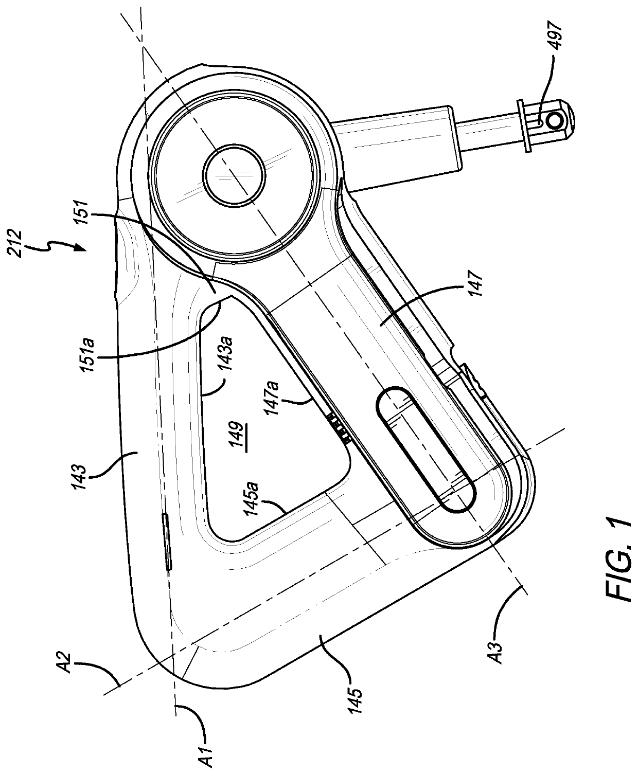
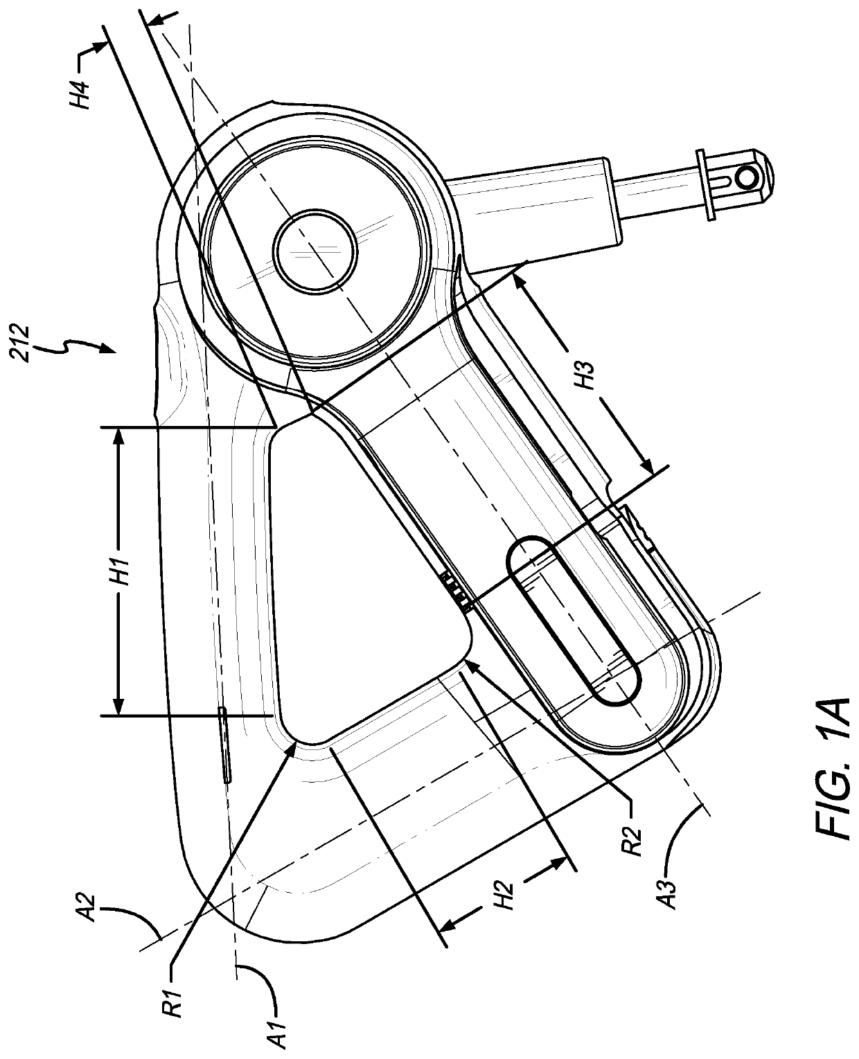
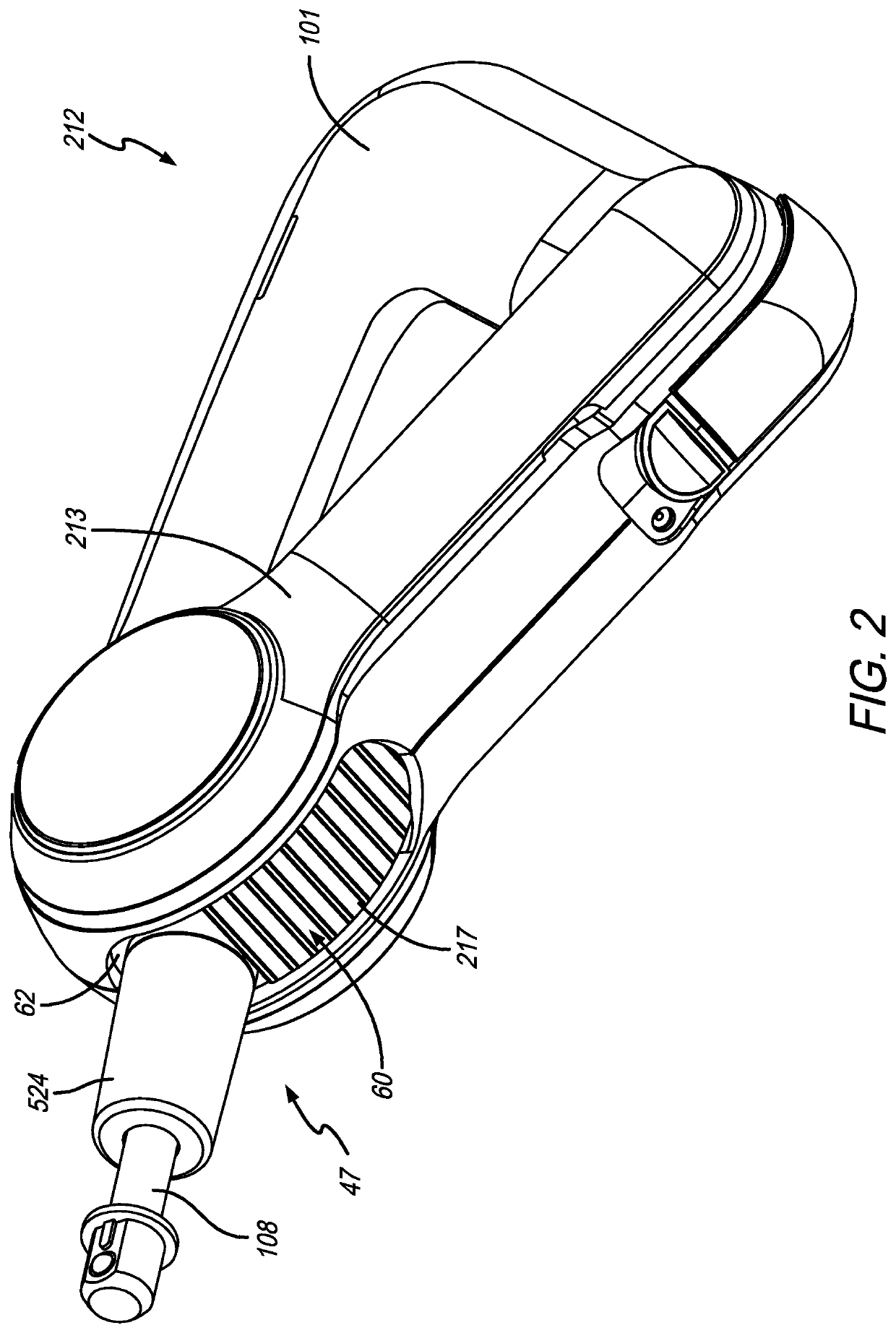
[0004]In accordance with a first aspect of the present invention there is provided a percussive therapy or percussive massage device that includes a housing, an electrical source, a motor positioned in the housing, a switch for activating the motor, and a routine controller configured to initiate a protocol configured to apply at least one output of the percussive therapy device in response to user input, and initiate at least one step of the protocol in which the percussive therapy device is applied in accordance with the at least one output. It will be appreciated that the terms percussive massage device and percussive therapy device are used interchangeably throughout. The terms are synonymous and generally have the same meaning. Commercial embodiments of the applicant's devices are generally being called percussive therapy devices in the market and therefore this term is used therein.

[0005]In a preferred embodiment, the at least one output comprises one or more of a time period ...


PUM


Abstract

A percussive therapy device that includes a housing, an electrical source, a motor positioned in the housing, a switch for activating the motor, and a routine controller configured to initiate a protocol configured to apply at least one output of the percussive therapy device in response to user input, and initiate at least one step of the protocol in which the percussive therapy device is applied in accordance with the at least one output.

Description

CROSS-REFERENCE TO RELATED APPLICATIONS[0001]This application is a continuation-in-part of U.S. patent application Ser. No. 16 / 796,143, filed Feb. 20, 2020, which claims the benefit of U.S. Provisional Application No. 62 / 844,424, filed May 7, 2019, U.S. Provisional Application No. 62 / 899,098, filed Sep. 11, 2019 and U.S. Provisional Application No. 62 / 912,392, filed Oct. 8, 2019. This application is also a continuation-in-part of U.S. patent application Ser. No. 16 / 675,772, filed Nov. 6, 2019, which claims the benefit of U.S. Provisional Application No. 62 / 785,151, filed on Dec. 26, 2018. All applications listed above are incorporated by reference herein in their entireties.FIELD OF THE INVENTION[0002]The present invention relates generally to massage devices and more particularly to a percussive therapy device that provides reciprocating motion.BACKGROUND OF THE INVENTION[0003]Massage devices often provide ineffective massages that are superficial and do not provide any real benefi...

Claims


Application Information

Patent Timeline
Patent Type & Authority Patents(United States)
IPC IPC(8): A61H23/00A61H23/02
CPCA61H23/006A61H23/00A61H23/02A61H23/0254A61H2201/0153A61H2201/149A61H2201/5007A61H2201/5043A61H2201/5061A61H1/00A61H2201/0165A61H2201/1207A61H2201/1669A61H2201/1685A61H2201/5025A61H2201/5035A61H2201/5046A61H2201/5097
Inventor WERSLAND, JASONNAZARIAN, BENJAMINSOLANA, JAIME SANCHEZMERINO, EDUARDO
Owner THERABODY INC
Why Eureka
Try Eureka