Top of rail applicator

a technology of applicators and rails, applied in the field of top of rail applicators, can solve the problems of high noise level, slip-stick oscillation, and common wear and tear of steel wheels and steel rails, and achieve the effect of placing friction control compositions on rails

Active Publication Date: 2021-03-30
WHITMORE MFG LLC
View PDF74 Cites 0 Cited by
  • Summary
  • Abstract
  • Description
  • Claims
  • Application Information

AI Technical Summary

Problems solved by technology

The emission of high noise levels and extensive wear of steel wheels and steel rails is a common problem in rail systems, including freight, passenger and mass transit trains.
Such problems are directly attributed to the frictional forces generated between the wheel and the railhead during operation of the system.
In addition to noise problems and extensive wear of the wheels and rails, negative friction between the two sliding steel surfaces cause slip-stick oscillations.
This, in turn, results in inefficient as well as sub-optimum performance.
Unfortunately, when compared to applicators placed on the side of the rail, TOR applicators, in direct contact with the train wheel, are more likely to be damaged or destroyed by train wheels.
However, such applicators have proved to be inadequate for a number of reasons.
As a result, the friction control composition is not effectively carried down the rail.
In other cases, substantial amounts of the friction control composition are wasted because the friction control composition ends up leaking down the sides of the rail and off the railhead.
In other instances, while prior art TOR applicators place the friction control composition on the railhead, the applicator itself is damaged or destroyed by impact when hit by train wheels.
Thus, such TOR applicators of the prior art become inoperable from impact damage.

Method used


Image

  • Top of rail applicator
  • Top of rail applicator
  • Top of rail applicator

Examples


Embodiment Construction

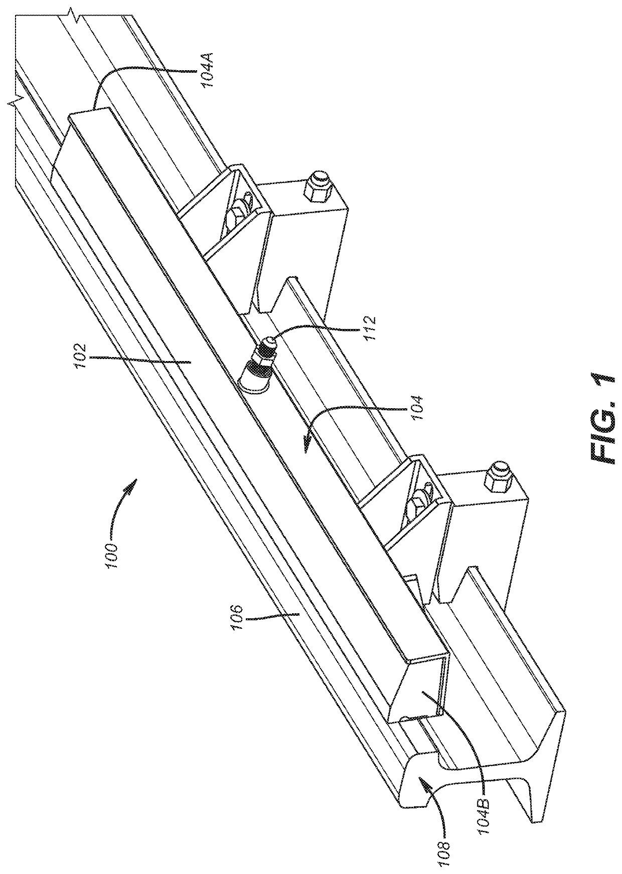
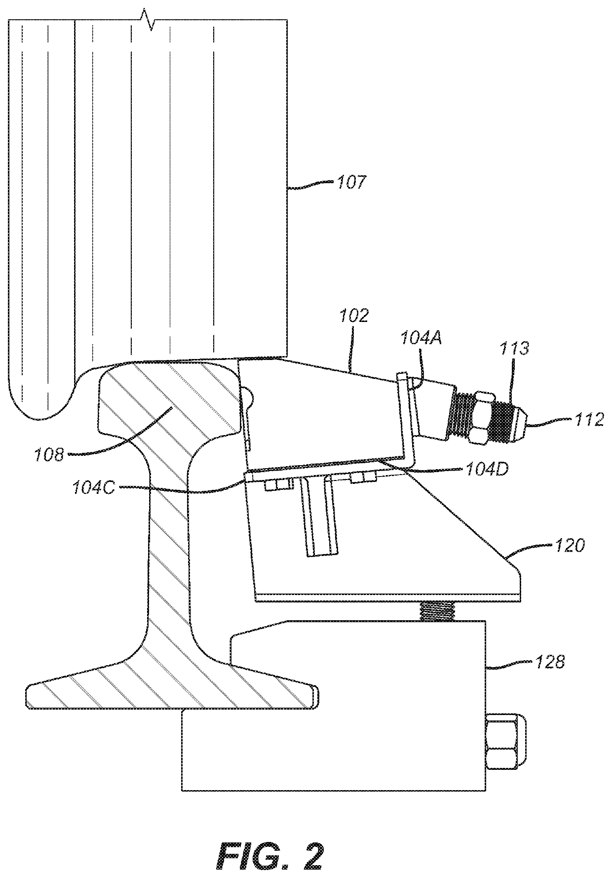
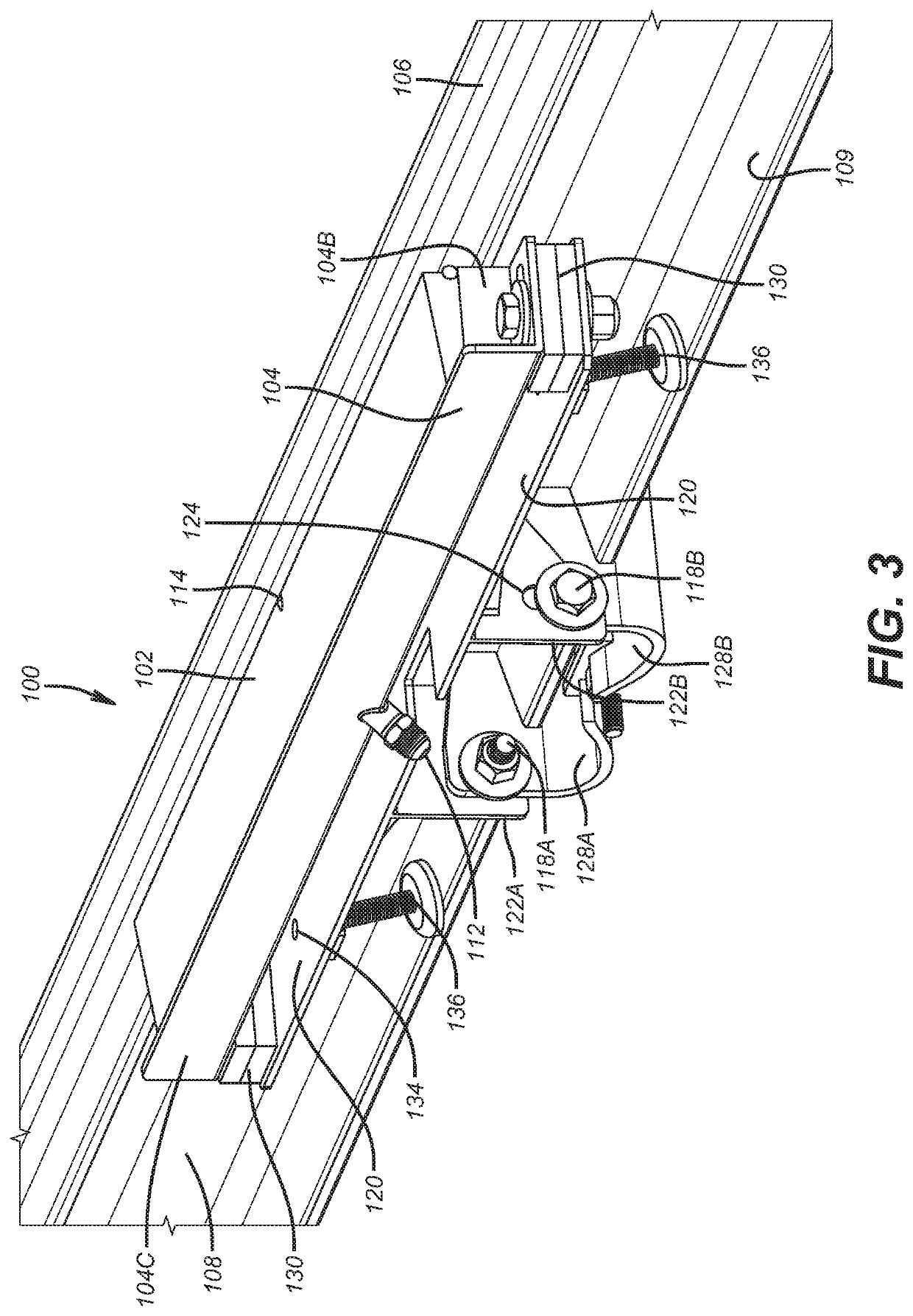
[0031]Characteristics and advantages of the present disclosure and additional features and benefits will be readily apparent to those skilled in the art upon consideration of the following detailed description of exemplary embodiments of the present disclosure and referring to the accompanying figures. It should be understood that the description herein and appended drawings, being of example embodiments, are not intended to limit the claims of this patent or any patent or patent application claiming priority hereto. On the contrary, the intention is to cover all modifications, equivalents and alternatives falling within the spirit and scope of the claims. Changes may be made to the particular embodiments and details disclosed herein without departing from such spirit and scope.

[0032]In showing and describing preferred embodiments in the appended figures, common or similar elements are referenced with like or identical reference numerals or are apparent from the figures and / or the d...


PUM

PropertyMeasurementUnit
diameteraaaaaaaaaa
longitudinal lengthaaaaaaaaaa

Abstract

A top of rail (TOR) applicator has a bar positioned in a housing and an exit orifice on the upper portion of the bar for delivering a friction control composition to the crown of a railhead. The upper portion of the bar slopes away from the friction control composition exit orifices. The bar may be composed of an elastomer such as polyurethane. Passageway extend from an inlet or entry orifice to the exit orifices. The friction reduction composition is pumped into the entry orifice, through the passageways to the exit orifices and then onto the crown of the railhead. The friction reduction composition may be thixotropic.

Description

[0001]This application claims the benefit of U.S. patent application Ser. No. 14 / 967,264, filed on Dec. 11, 2015, and U.S. patent application Ser. No. 62 / 124,240 filed on Dec. 12, 2014 and further is a continuation-in-part application of U.S. patent application Ser. No. 14 / 655,903, filed on Jun. 26, 2015, a national stage entry of PCT / US14 / 10188 which in turn claims the benefit of U.S. Patent Application Ser. No. 61 / 963,448, filed on Dec. 4, 2013; U.S. Patent Application Ser. No. 61 / 962,265 filed on Nov. 4, 2013; U.S. Patent Application Ser. No. 61 / 958,789, filed on Aug. 6, 2013; U.S. Patent Application Ser. No. 61 / 850,923 filed on Feb. 26, 2013; U.S. Patent Application Ser. No. 61 / 850,690, filed on Feb. 21, 2013; U.S. Patent Application Ser. No. 61 / 848,596, filed on Jan. 7, 2013; all of which are herein incorporated by reference.FIELD OF THE DISCLOSURE[0002]The disclosure relates to an applicator for delivery of a friction control composition to a railhead.BACKGROUND OF THE DISCLOS...

Claims


Application Information

Patent Timeline
Patent Type & Authority Patents(United States)
IPC IPC(8): B61K3/00C10M173/00C10M105/08C10M105/04C10N30/02C10N30/06C10N30/12
CPCB61K3/00C10M173/00C10M105/04C10M105/08C10M2201/02C10M2203/02C10M2207/40C10N2030/02C10N2030/06C10N2030/12
Inventor ANDERSON, STEVE DONALDADKINS, KEVIN RAYKRINKER, RANDALLCHIDDICK, KELVINWILSON, KYLE
Owner WHITMORE MFG LLC
Why Eureka
Try Eureka