Piezoelectric element for an automatic frequency control circuit, oscillating mechanical system and device comprising the same

a technology of automatic frequency control circuit and piezoelectric element, which is applied in the field of pie, can solve the problems of inability to precisely and optimally use the piezoelectric effect of the element without significantly complicating the design of the system, and the extra step of spring manufacture,

Active Publication Date: 2021-04-06
THE SWATCH GRP RES & DEVELONMENT LTD
View PDF11 Cites 3 Cited by
  • Summary
  • Abstract
  • Description
  • Claims
  • Application Information

AI Technical Summary

Benefits of technology

[0009]It is therefore an object of the invention to provide a piezoelectric element for an automatic frequency control circuit, which is simple to realize and allows the piezoelectric effect to be used in a precise and optimum manner, in order to precisely control the oscillation frequency of the oscillating mechanical system, and to overcome the aforementioned drawbacks of the state of the art.
[0016]Using a piezoelectric crystal for the balance spring makes it possible to make the piezoelectric element in a simple and economical manner, while maintaining good piezoelectric performance. Further, the particular arrangement of the first and second electrodes in a predetermined angular distribution over the spring allows the electrodes to collect part of the electrical charges generated by a mechanical stress, overcoming the problem of the change in polarity of the charges due to the change in crystal orientation of the piezoelectric crystal. This change in polarity of the charges occurs with periodic angular distribution in the balance spring. Indeed, the crystalline structure of the piezoelectric material induces a dependence of the piezoelectric coefficient on the orientation of the mechanical stress in a horizontal plane XY. In other words, depending on the direction of the stress in plane XY, the electrical charges created may be positive or negative, and their value comprised between a zero value and a maximum value, as illustrated, for example, in FIG. 2 in the case of quartz. As a result of the piezoelectric element according to the invention, the problem of positive and negative charges cancelling each other in each of the electrodes is overcome. In a non-limiting manner within the scope of the present invention, the piezoelectric crystal is, for example, a single quartz crystal.
[0017]According to a first embodiment of the invention, the first and second electrodes are disposed on one portion of an outer coil of the balance spring, said portion including one end of the balance spring and defining a predetermined angular sector. One advantage of this first embodiment is the simplicity of manufacture of the piezoelectric element, and in particular of its electrodes.
[0019]One advantage of this second embodiment is that it maximises collection of the electrical charges generated, and thus maximises the amount of electrical energy collected.
[0020]Advantageously, the piezoelectric element includes a first groove made in the first side of the strip of piezoelectric material, and a second groove made in the second side of the strip of piezoelectric material. The first electrode is at least partially disposed in the first groove, and the second electrode is at least partially disposed in the second groove. This makes it possible to increase the capacitive coupling between the electrodes, and thereby increase the piezoelectric performance of the element.

Problems solved by technology

However, depositing such piezoelectric films over the entire length of the balance spring introduces an expensive extra step into the manufacture of the spring, which is a drawback.
However, one drawback of the proposed piezoelectric element is that the piezoelectric effect of the element cannot be used in a precise and optimum manner without considerably complicating the design of the system.

Method used


Image

  • Piezoelectric element for an automatic frequency control circuit, oscillating mechanical system and device comprising the same
  • Piezoelectric element for an automatic frequency control circuit, oscillating mechanical system and device comprising the same
  • Piezoelectric element for an automatic frequency control circuit, oscillating mechanical system and device comprising the same

Examples


Embodiment Construction

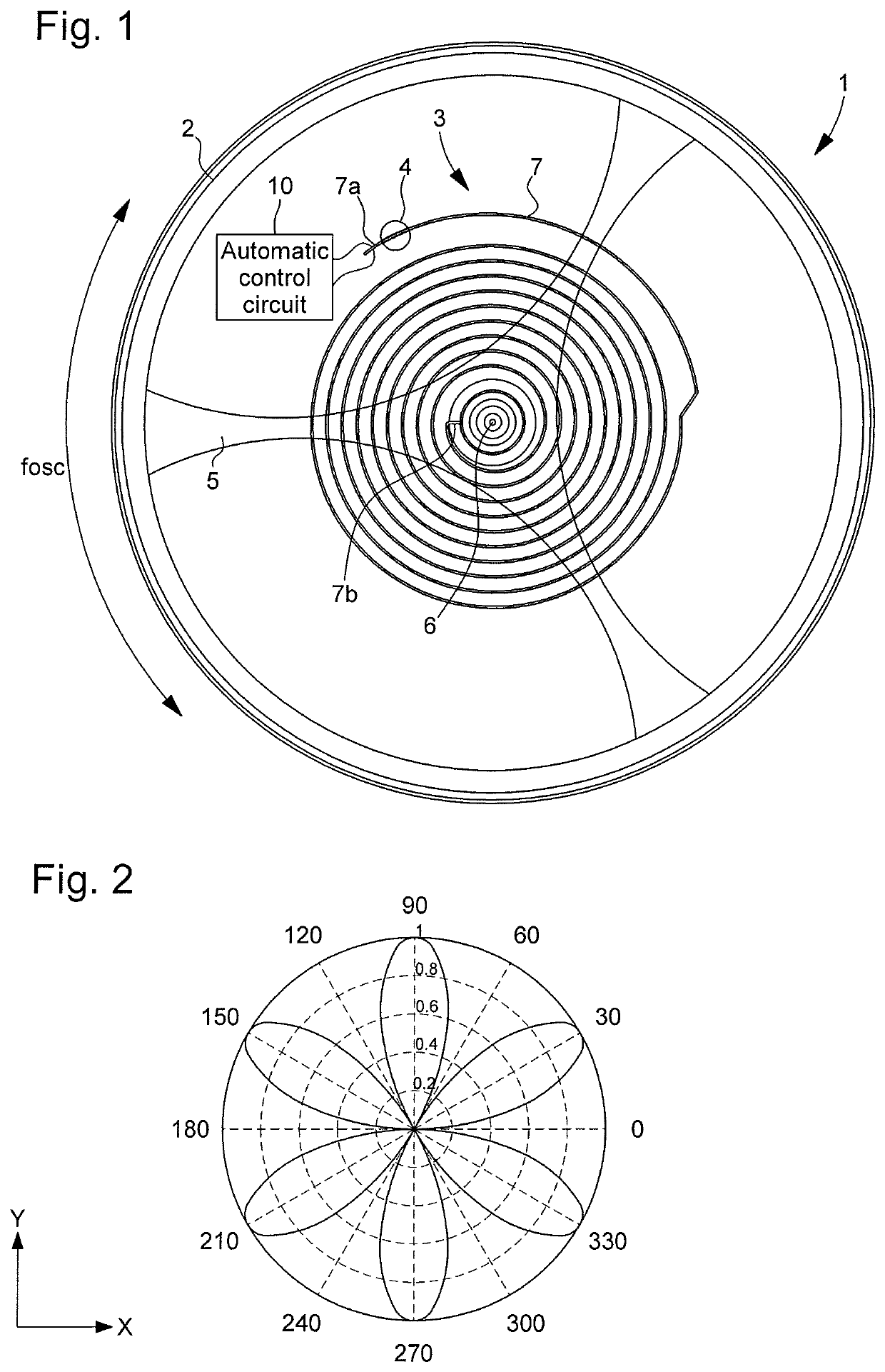
[0039]In the following description, reference is made to a piezoelectric element for an automatic frequency control circuit, particularly a circuit for automatic control of the oscillation frequency of an oscillating mechanical system. All the electronic components of the automatic frequency control circuit that are well known to those skilled in the art in this technical field will be described only in a simplified manner. As described below, the automatic control circuit is mainly used for controlling the oscillation frequency of a balance on which is mounted the balance spring of the piezoelectric element. However, other oscillating mechanical systems may also be envisaged, but in the following description, reference will be made only to an oscillating mechanical system in the form of a balance on which is mounted the balance spring of the piezoelectric element.

[0040]FIG. 1 shows a device 1, which includes an oscillating mechanical system 2, 3 and a circuit 10 for automatic contr...


PUM


Abstract

A piezoelectric element for an automatic frequency control circuit. The element includes a balance spring formed of a piezoelectric crystal strip, a first electrode connected to the automatic control circuit, and disposed on at least a first side of the strip, and a second electrode connected to the automatic control circuit and disposed on at least a second side of the strip. The first and second electrodes are placed on one portion or over the entire length of the balance spring in a predetermined angular distribution.

Description

[0001]This application claims priority from European Patent Application No. 17191147.2 filed on Sep. 14, 2017; the entire disclosure of which is incorporated herein by referenceFIELD OF THE INVENTION[0002]The invention concerns a piezoelectric element for an automatic frequency control circuit.[0003]The invention also concerns an oscillating mechanical system comprising the piezoelectric element and a balance.[0004]The invention also concerns a device comprising the oscillating mechanical system and a circuit for automatic control of the oscillation frequency of the oscillating mechanical system.BACKGROUND OF THE INVENTION[0005]Piezoelectric elements are commonly used in the field of electromechanical systems, for example for making oscillators used as time bases, or for applications for mass, force, gyroscope sensors and many others.[0006]In the field of horology, and particularly of mechanical or electromechanical watches, it is known to provide an oscillating mechanical system wi...

Claims


Application Information

Patent Timeline
Patent Type & Authority Patents(United States)
IPC IPC(8): G04C3/04G04B17/06G04B17/22
CPCG04C3/047G04B17/066G04B17/227H03H3/04H03H9/02023H03H9/19H03H2003/0414
Inventor HAEMMERLI, ALEXANDREGUEISSAZ, FRANCOISTOMBEZ, LIONELSCHNYDER, BERNHARDDALLA PIAZZA, SILVIO
Owner THE SWATCH GRP RES & DEVELONMENT LTD
Why Eureka
Try Eureka