
All seeing one camera system for electronic tolling

a technology of electronic tolling and camera system, applied in the direction of traffic movement detection, instruments, computing, etc., can solve the problems of labor-intensive, costly, and disadvantageous tolling systems, and achieve the effects of enhancing the capability to determine the identification of vehicles, high imaging speed, and optimizing resolution

Active Publication Date: 2021-04-06
VERTEX AEROSPACE LLC
View PDF21 Cites 0 Cited by
  • Summary
  • Abstract
  • Description
  • Claims
  • Application Information

AI Technical Summary

Benefits of technology

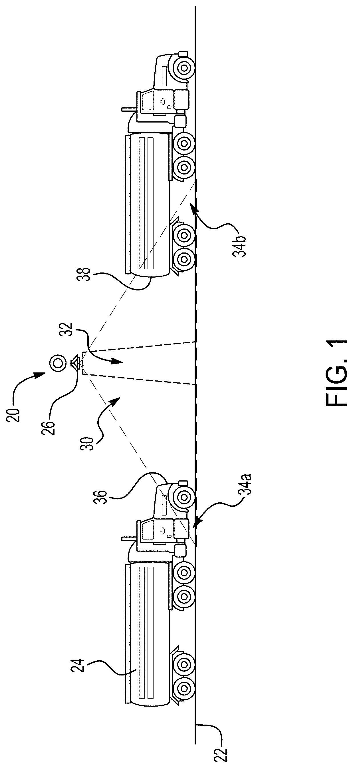
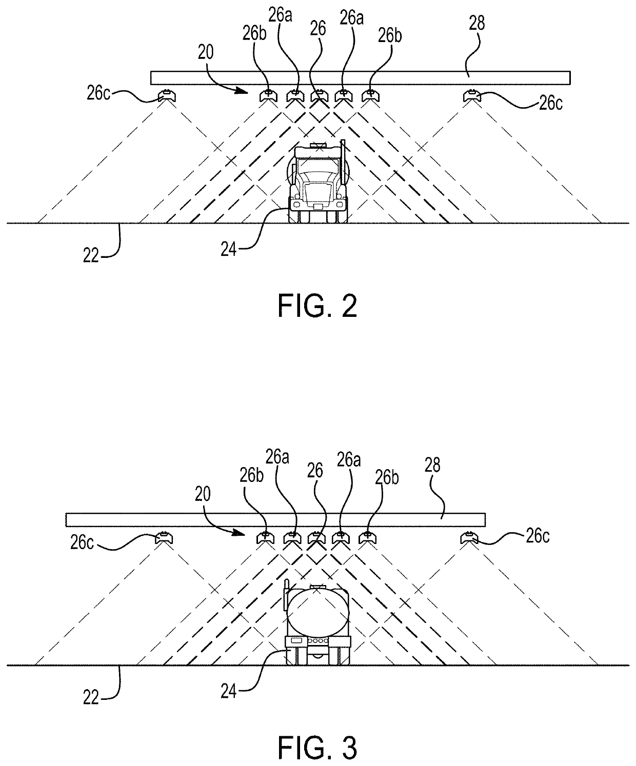
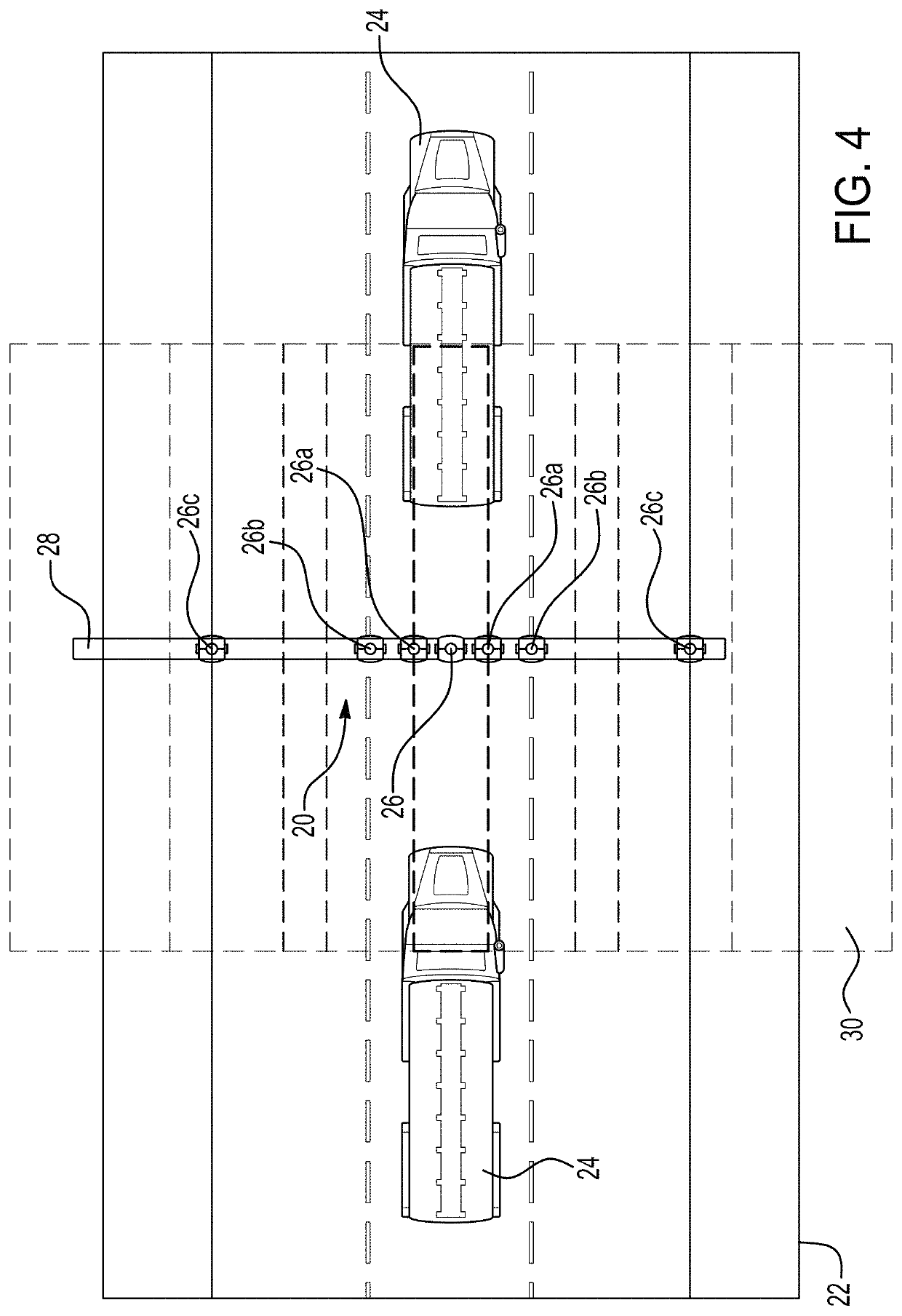
The All Seeing One Camera (ASOC) method and system for electronic tolling of a vehicle involves using a single camera or a camera array to capture images of a vehicle traveling on a road surface. The camera is positioned normal to the road surface and has a field-of-view that ensures optimal resolution for reading the license plate of the vehicle. The captured images can be used to identify the vehicle, track it, determine its size or shape, and classify it based on the number of axles. The ASOC system uses a high-speed camera, ultra-wide-angle lens, and a light source providing uniform lighting, resulting in a more efficient tolling system with lower costs.

Problems solved by technology

However, the conventional tolling systems are disadvantageous due to the complexity and costs associated with installation and maintenance of the numerous components to complete a single transaction.
For example, the in-pavement installation of loops requires precise alignment and is particularly labour intensive and costly to close the roadway to cut into the highway pavement.

Method used


Image

  • All seeing one camera system for electronic tolling
  • All seeing one camera system for electronic tolling
  • All seeing one camera system for electronic tolling

Examples


Embodiment Construction

[0047]The principles described herein have particular application in electronic tolling systems used on toll roads for transaction purposes. FIGS. 1-4 shows an All Seeing One Camera (ASOC) system 20 according to the present application. The ASOC system 20 is arranged relative to a road surface 22 along which a vehicle 24 travels. The road surface 22 may be any suitable section of a road, such as a highway or a toll road on which the vehicle 24 may travel between 0 (stop-and-go) and 150 kilometers per hour (between 0 and 93 miles per hour). The vehicle 24 may be any suitable vehicle having any number of wheels. For example, the vehicle 24 may be a motorcycle or other two-wheeled vehicle, a four-wheeled car, truck, or van, or any vehicle having more than four wheels, such as a semi-trailer truck. The vehicle 24 may include a powered vehicle and one or more attached unpowered wheeled vehicle or unit, such as a trailer, a towed boat, or a towed car.

[0048]The ASOC system 20 includes a si...


PUM


Abstract

A method of electronic tolling for a vehicle travelling on a road surface includes providing a single camera or a single array of cameras, arranging the single camera or the single array of cameras to have a field-of-view that is normal to the road surface and is defined by a plane that is parallel with the road surface, and capturing multiple images of the front, side, top and rear of the vehicle using the single camera or the single array of cameras in the field-of-view. The set of multi-perspective images can be used to identify a vehicle by reading the front and rear license plate and to determine a classification of the vehicle. The images may also be used to track the position of the vehicle on the road surface as the vehicle traverses the field-of-view.

Description

RELATED APPLICATIONS[0001]This application claims the benefit of U.S. Provisional Application No. 62 / 750,872 filed Oct. 26, 2018, which is hereby incorporated herein by reference in its entirety.FIELD OF THE INVENTION[0002]The invention relates to automated electronic tolling systems used for transactions, and more particularly to cameras for electronic tolling systems.DESCRIPTION OF THE RELATED ART[0003]An All Electronic Tolling (AET) system consists of video, classification and transponder subsystems. The AET system uses the detection of a front end and a rear end of a vehicle to capture images of the license plates of the vehicle, and other images of the vehicle. The license plate images may be used to identify the vehicle for transaction purposes, such as for paying a toll on a toll road portion of a highway. Conventional tolling systems require a vehicle to pass a predetermined point on the toll road where a triggering device is triggered to command a camera to take an image of...

Claims


Application Information

Patent Timeline
Patent Type & Authority Patents(United States)
IPC IPC(8): G07B15/00G06K9/32G08G1/017G06K9/00G06V10/147
CPCG07B15/00G06K9/00771G06K9/325G08G1/0175G06K2209/15G07B15/06G08G1/0116G08G1/015G08G1/04G08G1/056G06V20/54G06V10/147G06V20/625G06V20/52G06V20/62
Inventor GILLIES, ROBERT M.
Owner VERTEX AEROSPACE LLC
Learn More