Securing device for a decoupling device on a shielding part, decoupling device having the securing device, and shielding part having the decoupling device

a technology of shielding part and decoupling device, which is applied in the direction of mechanical equipment, machines/engines, transportation and packaging, etc., can solve the problems of promoting unwanted corrosion and requiring an undesirably large amount of installation work for the proposed fastening device, and achieves uniform force introduction and advantageous material thickness.

Active Publication Date: 2021-04-13
ELRINGKLINGER AG
View PDF53 Cites 2 Cited by
  • Summary
  • Abstract
  • Description
  • Claims
  • Application Information

AI Technical Summary

Benefits of technology

[0006]In this regard, a functional combination is achieved, which leads to the fact that the fastening device requires fewer components as compared to the prior art. Moreover, it is possible to eliminate installation steps of an additional connecting device for attachment to the bridge element.
[0008]This makes it possible, in a particularly simple way, to fasten the outer edge of a one-layer bridge element to the hole rim of the shielding part in an immobilized fashion.
[0012]With such an embodiment of the fastening device and an installation of such a decoupling device having this embodiment of the fastening device on a shielding part, the tabs of the individual parts—because of the reach-through points being situated inside the hole rim of the shielding part and an attachment of the tabs to the shielding part being situated outside the reach-through point—constitute an additional fixing of the individual parts relative to each other in an axial direction. In the vicinity of the reach-through point, the individual parts are supported against each other and thus constitute a short path for a flow of force. Furthermore, the reaching-through ensures that with a transmission of axial forces that are to be transmitted between the decoupling device and the shielding part, the two individual parts of the bridge element are always involved in the transmission of axial force.
[0013]In another preferred embodiment of the fastening device, in a preinstallation position of the decoupling device, the tabs of the subset or the tabs of the remainder are bent radially inward so that the decoupling device can be inserted into the hole opening in the shielding part in such a way that the other tabs extending radially outward can be brought into contact with the associated outside of the shielding part. Such an embodiment makes it possible for the decoupling device having the fastening device according to the invention to be embodied so that it can be preassembled in module-like fashion and in a preassembled state, for it to be inserted as a unit into the associated opening in the shielding part and in the inserted state, to fasten it merely by bending the tabs, which were initially bent radially inward, outward onto the shielding part. Another preferred embodiment of the fastening device is characterized in that the tabs of the subset and the tabs of the remainder are arranged one after the other in alternating fashion viewed in the circumference direction U. Such an embodiment of the fastening device ensures a particularly uniform force introduction of holding forces into the hole rim of the shielding part or conversely from the hole rim of the shielding part into the decoupling device. Another advantageous embodiment of the fastening device features the fact that in the installed state, cut edges of a space bottom of the spaces of the one individual part are supported resting against the tabs of the other part. This makes it possible, in the vicinity of the point where the tabs reach through the spaces of the other tabs, to ensure a support of the individual parts relative to one another and thus to implement the short flow-of-force path already mentioned above.

Problems solved by technology

The proposed fastening device requires an undesirably large amount of installation work because the fastener must first be attached to the decoupling device and then the combined decoupling device and fastener must be attached to the shielding part.
In addition, a large number of material folds occur in the region of the hole rim, which can promote unwanted corrosion, particularly during operation of the shielding part.

Method used


Image

  • Securing device for a decoupling device on a shielding part, decoupling device having the securing device, and shielding part having the decoupling device
  • Securing device for a decoupling device on a shielding part, decoupling device having the securing device, and shielding part having the decoupling device
  • Securing device for a decoupling device on a shielding part, decoupling device having the securing device, and shielding part having the decoupling device

Examples


Embodiment Construction

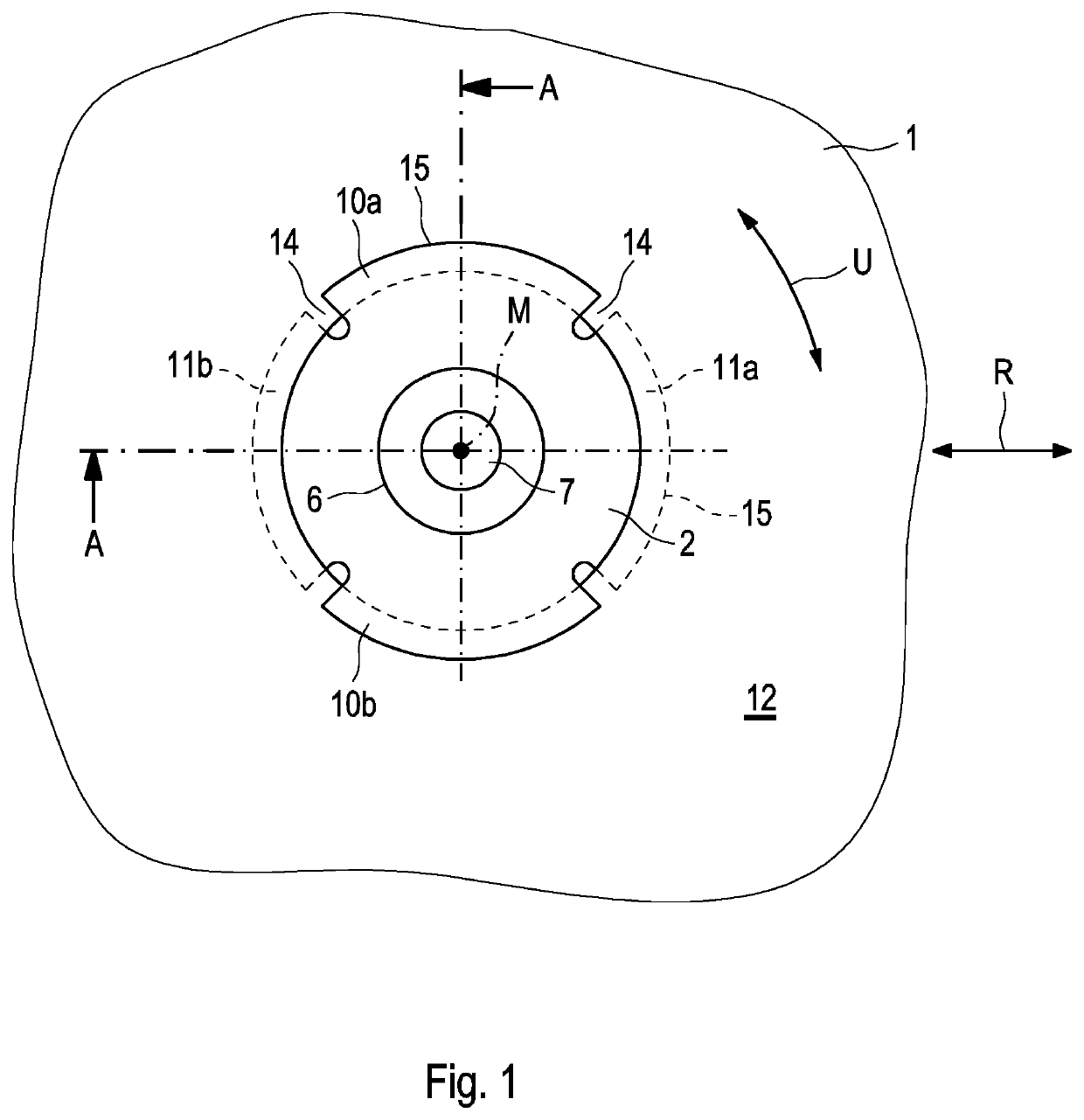
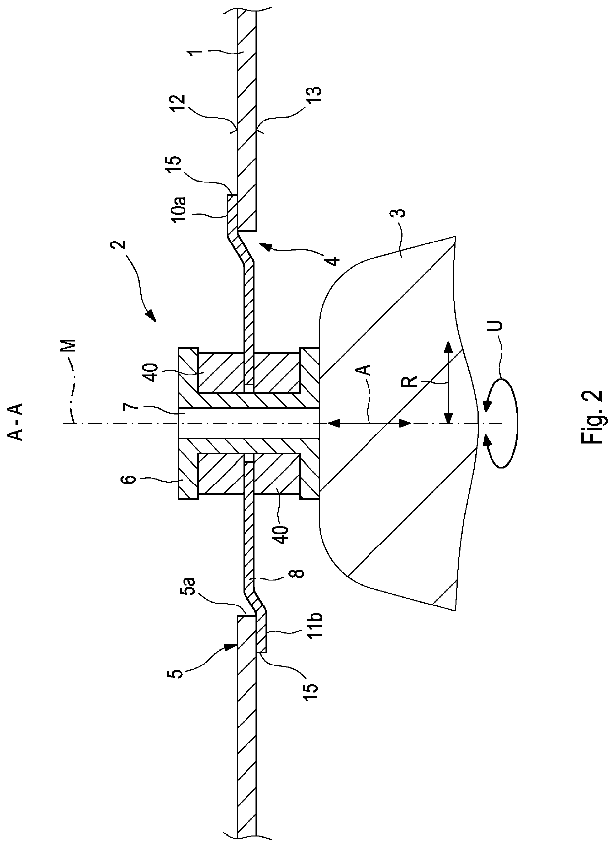
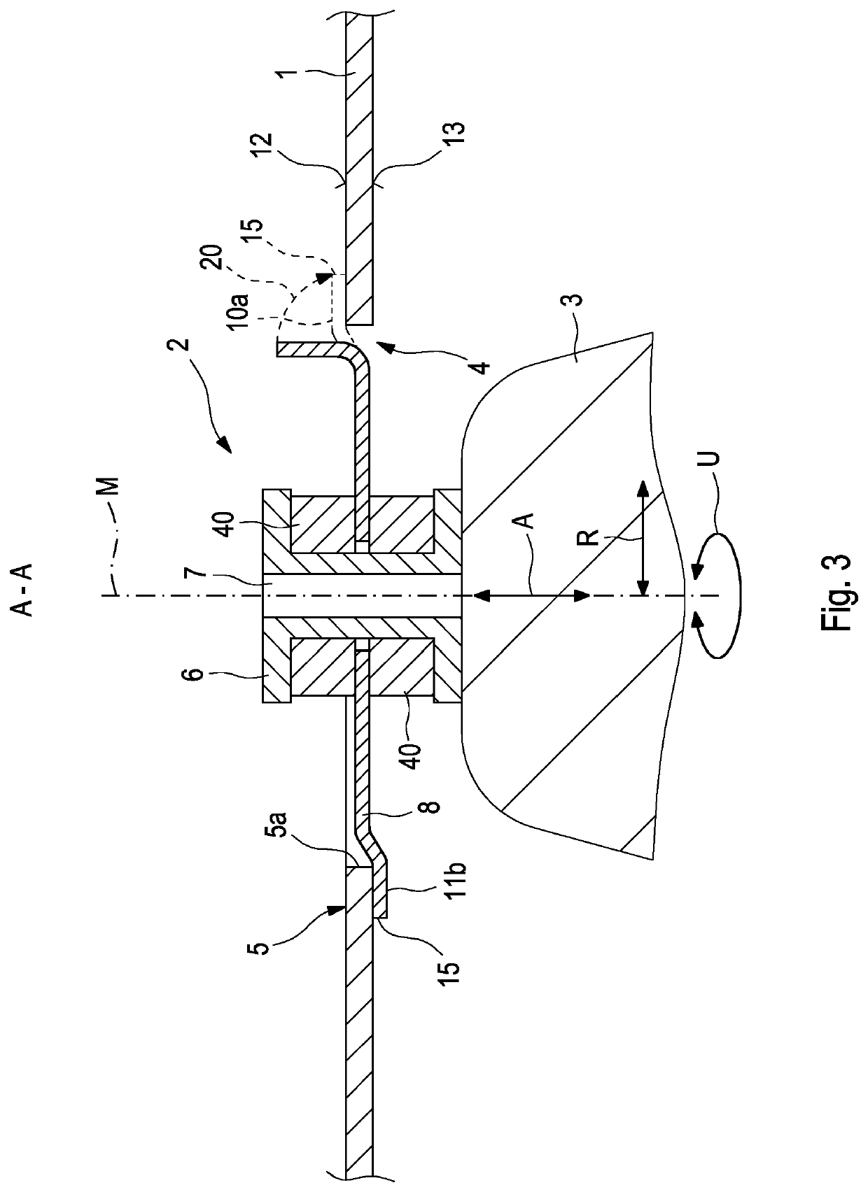
[0025]A first embodiment of the invention will be explained in greater detail below by way of example based on FIGS. 1 through 3.

[0026]A shielding part 1 is usually embodied as a broad one-layer or multi-layer sheet metal layer, e.g. composed of aluminum or steel, in particular stainless steel. Such a shielding part is usually used as a heat shield; for example, such a heat shield is used in automotive engineering in the vicinity of hot components, e.g. exhaust manifolds, catalytic converters, turbochargers, or the like. One object of such a heat shield is to keep radiated heat away from components that are more sensitive to heat exposure in the vicinity of the hot component.

[0027]During operation, in addition to a heat exposure, shielding parts 1 of this kind are usually also subject to a vibration impingement and for the fastening of the shielding part 1, have at least one, but preferably several decoupling devices 2 on a fastening counterpart 3. The fastening counterpart 3 can be...


PUM


Abstract

A fastening device for fastening a decoupling device relative to a hole rim of a hole opening of a shielding part; to achieve the vibration-decoupling connection of a bushing to the shielding part, the decoupling device has at least one bridge element, which, at its radially outer edge, has fasteners for producing a fastening connection of the bridge element to the hole rim of the shielding part, wherein the fasteners comprise at least four tabs which, starting from the bridge element, protrude radially outward and a subset of at least two tabs of the bridge element is provided to rest against a first outside of the shielding part and a remainder of at least two tabs is provided to rest against an opposite second outside of the shielding part and the hole rim can be immobilized with a force fit relative to the decoupling device by means of the tabs of the subset and the tabs of the remainder.

Description

FIELD OF THE INVENTION[0001]The invention relates to a fastening device for fastening a decoupling device relative to a hole rim of a hole opening of a shielding part. The invention also relates to a decoupling device having the fastening device and to a shielding part.BACKGROUND OF THE INVENTION[0002]A fastening device having the features of the preamble to claim 1 is known from DE 60 2004 002 062 T2. In its radially outer region, a bridge element for connecting a bushing to a shielding part has a fastener for connecting the outer edge of the bridge element to a hole rim of the shielding part. Such a fastener is disclosed as a ring with an s-shaped cross-section, which at one end, embraces the edge of the bridge element and at the other, embraces the hole rim with a folded-over collar. The proposed fastening device requires an undesirably large amount of installation work because the fastener must first be attached to the decoupling device and then the combined decoupling device an...

Claims


Application Information

Patent Timeline
Patent Type & Authority Patents(United States)
IPC IPC(8): B60R13/08F01N13/10F01N13/14F01N13/18F16B5/02
CPCB60R13/0876F01N13/102F01N13/14F01N13/1811F16B5/0241B60R2013/0807F01N13/1855F01N2260/20F01N2450/24
Inventor HEISELBETZ, GERALD
Owner ELRINGKLINGER AG
Why Eureka
Try Eureka