Self-locking belt retractor for a seat belt device of a motor vehicle

a technology of self-locking belt and seat belt, which is applied in the direction of belt retractors, vehicle safety belts, vehicle components, etc., can solve the problem that the load on the associated seat belt can exceed the set load limit, and achieve the effect of reducing serious injuries

Active Publication Date: 2021-04-13
AUTOLIV DEV AB
View PDF9 Cites 0 Cited by
  • Summary
  • Abstract
  • Description
  • Claims
  • Application Information

AI Technical Summary

Benefits of technology

[0018]It is further recommended that the insert component exhibits a thread which is coaxial to a rotational axis of the belt shaft body in its assembled state, with which it is screwed together with a correspondingly shaped thread of the belt shaft body for the purpose of enabling relative rotational movement. Through this threaded connection, an axial connection of the insert component with the belt shaft body is achieved. Additionally, with an appropriate choice of thread direction it is possible that the belt shaft body performs a predetermined relative rotational movement and thereby a forced axial movement in relation to the insert component when the force-limiting device is active.
[0012]With the recommended solution, the belt retractor can be designed better with respect to the requirements, in that the profile head is designed as two components, wherein the carrier component is specially designed with consideration of the mounting and guiding of the blocking catch, while the insert component is specially designed for receiving and transmitting the reaction forces. The functions of mounting and guiding the blocking catch are thereby practically separated from the function of force transmission. To this end, the insert component specially exhibits a higher deformation resistance than the carrier component and, in the blocked state of the blocking catch, forms the force transfer connection between the blocking catch and the force-limiting device. The force exerted by the belt shaft body is introduced via the insert component with bridging of the carrier component directly through the blocking catch into the vehicle-affixed interlock. The carrier component of the profile head can thereby be optimized with respect to the choice of material, the manufacturing process, and especially with respect to the forming process and the associated costs, without taking into account the reaction forces which must be absorbed. The assembly of the two-component profile head and the insert component thus constitutes a hybrid, which with respect to the requirements can be designed better.
[0014]It is further recommended that the insert component exhibits a fixing section, and the carrier component exhibits a second recess which corresponds in shape to the shape of the fixing section and with which the insert component with the fixing section engages to form a positive-locking connection. With the recommended solution, the insert component and the profile head form a non-rotatable connection until activation of the force-limiting device. If the insert component is also non-rotatably connected to the belt shaft body, it also serves to provide a non-rotatable connection of the profile head with the belt shaft body up to the force-limiting level defined by the force-limiting device. As the insert component in the area of the fixing section is intentionally designed and disposed to absorb the reaction forces, the blocking of the belt shaft takes place reliably and without placing load on the carrier component of the profile head.
[0014]It is further recommended that the insert component exhibits a fixing section, and the carrier component exhibits a second recess which corresponds in shape to the shape of the fixing section and with which the insert component with the fixing section engages to form a positive-locking connection. With the recommended solution, the insert component and the profile head form a non-rotatable connection until activation of the force-limiting device. If the insert component is also non-rotatably connected to the belt shaft body, it also serves to provide a non-rotatable connection of the profile head with the belt shaft body up to the force-limiting level defined by the force-limiting device. As the insert component in the area of the fixing section is intentionally designed and disposed to absorb the reaction forces, the blocking of the belt shaft takes place reliably and without placing load on the carrier component of the profile head.
[0021]It is further recommended that the insert component is pressed over protruding projections in correspondingly shaped openings of the carrier component. The insert component and the carrier component thus form a connection and can be regarded as a two-part profile head as an assembly which is fixed against rotation up to a certain force.
[0016]It is further recommended that the blocking catch is mounted in a first recess of the carrier component, and that the first recess exhibits an opening through which the blocking catch abuts the insert component. The first recess exhibits a special contour, through which the movement of the blocking catch is, inter alia, guided into the blocked position. To this end, the blocking catch must necessarily rest on one or more walls of the first recess in its various positions, so that no uncontrolled or undesired movements can occur. According to the invention, at least one wall of the first recess, which is very important for guiding the blocking catch, is now interrupted by an opening, so that the blocking catch with bridging of the carrier component can preferably rest or come to rest directly on the insert component.
[0017]It is further recommended that the activation of the force-limiting device is limited by a stop, whereby a progressive force-limiting characteristic or also stop characteristic (LLS) can be achieved.
[0018]It is further recommended that the insert component exhibits a thread which is coaxial to a rotational axis of the belt shaft body in its assembled state, with which it is screwed together with a correspondingly shaped thread of the belt shaft body for the purpose of enabling relative rotational movement. Through this threaded connection, an axial connection of the insert component with the belt shaft body is achieved. Additionally, with an appropriate choice of thread direction it is possible that the belt shaft body performs a predetermined relative rotational movement and thereby a forced axial movement in relation to the insert component when the force-limiting device is active.
[0019]In this case, the stop can thus preferably be disposed such that it limits the relative rotational movement enabled by the thread. This can be achieved, for example, in that the thread pair is pulled flush, or that a stop is provided on one of the threads to block further rotational movement. Thus the load limiting element (torsion bar) is not capable of further torsional deformation and the load on the associated seat belt can increase beyond the set load limiting threshold.

Problems solved by technology

Thus the load limiting element (torsion bar) is not capable of further torsional deformation and the load on the associated seat belt can increase beyond the set load limiting threshold.

Method used


Image

  • Self-locking belt retractor for a seat belt device of a motor vehicle
  • Self-locking belt retractor for a seat belt device of a motor vehicle
  • Self-locking belt retractor for a seat belt device of a motor vehicle

Examples


Embodiment Construction

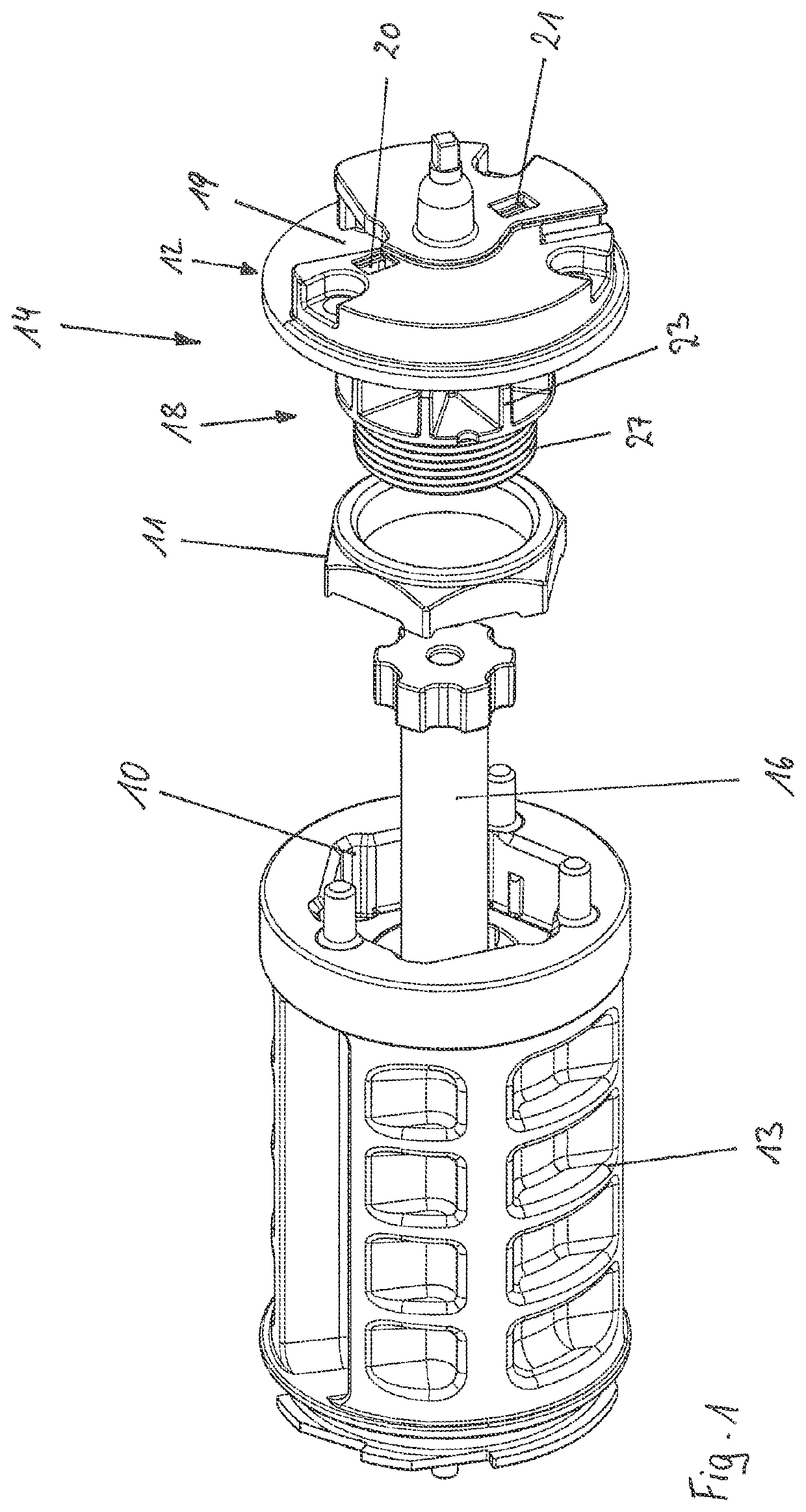
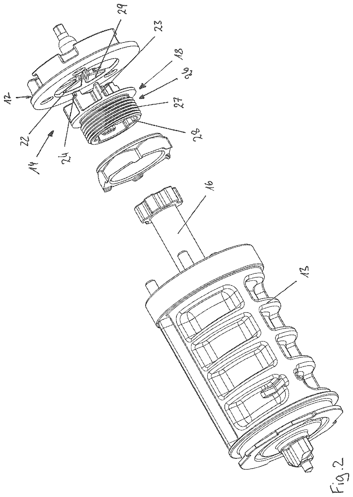
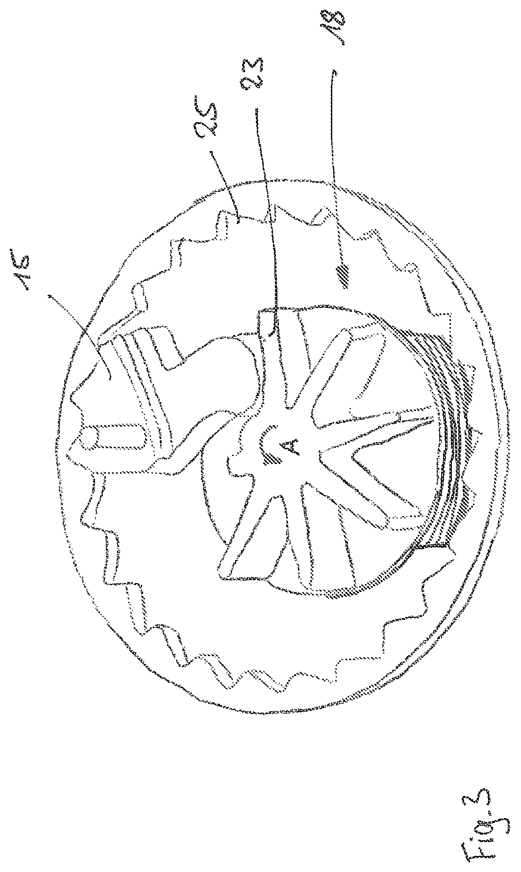
[0026]In FIGS. 1 and 2 respectively, a self-locking belt retractor according to the invention can be seen in various views in exploded view. The belt retractor includes a U-shaped frame (not shown) with two opposing legs, in each of which an opening is provided. The belt retractor is affixed to the vehicle via the frame, either onto the vehicle structure or on a vehicle seat. Furthermore, the belt retractor includes a belt shaft body 13, a profile head 14, and a torsion bar 16, which is mounted in the openings of the legs of the frame. The belt shaft body 13 serves to wind up a seat belt, while a first recess 19 is provided on the profile head 14, in which a blocking catch, only seen in FIG. 3, is mounted such that it can swivel. The torsion bar 16 is non-rotatably connected on a first end with the belt shaft body 13 and on a second end with the profile head 14 and forms a force-limiting device which will be subsequently described in greater detail.

[0027]The blocking catch 15 is par...


PUM


Abstract

A self-locking belt retractor for a seat belt device of a motor vehicle with a belt shaft body and a profile head, and a blocking device with a blocking catch mounted on the profile head. When activated, the blocking device engages in a blocked position with a vehicle-affixed interlock for the purpose of blocking the belt shaft in the belt extension direction. A force-limiting device is disposed in the force transmission path from the belt shaft body to the blocking catch. The profile head is made as two parts, with a carrier component and an insert component which are affixed together. The insert component exhibits a higher resistance to deformation than the carrier component and, when the belt shaft is blocked, forms part of the force transmission path between the blocking catch and the force-limiting device.

Description

CROSS-REFERENCE TO RELATED APPLICATION[0001]This application claims the benefit of priority under 35 U.S.C. § 119 to German Patent Application No. 10 2018 106 664.3, filed Mar. 21, 2018, the contents of which are incorporated herein by reference in their entirety.FIELD OF THE INVENTION[0002]The invention relates to a self-locking belt retractor for a seat belt device of a motor vehicle.BACKGROUND AND INTRODUCTORY DESCRIPTION OF THE INVENTION[0003]Seat belt devices in motor vehicles serve to restrain a passenger in the event of an accident, to reduce serious injuries. The seat belt devices thereby include a seat belt, which is affixed to the vehicle at one end with an end fitting and affixed at the other end to a belt shaft of a belt retractor, which is affixed to the vehicle. Furthermore, a movable belt tongue is provided on the seat belt, which can be locked into a belt buckle, which is also affixed to the vehicle, in order to create a 3-point geometry.[0004]The belt retractor can ...

Claims


Application Information

Patent Timeline
Patent Type & Authority Patents(United States)
IPC IPC(8): B60R22/46
CPCB60R22/46B60R22/34B60R22/26B60R22/3413
Inventor STRUTZ, MICHAELSUHR, STEFANWERNER, CHRISTOPHER
Owner AUTOLIV DEV AB
Why Eureka
Try Eureka