
Electronic parking brake system and control method thereof

a technology of electronic control unit and electric brake, which is applied in the direction of braking system, vehicle sub-unit features, braking components, etc., can solve the problems of motor failure and electronic control unit may determine the failure of the electric motor, and achieve the effect of accurately and reliably determining the failure of the motor

Active Publication Date: 2021-04-13
HL MANDO CORP
View PDF18 Cites 0 Cited by
  • Summary
  • Abstract
  • Description
  • Claims
  • Application Information

AI Technical Summary

Benefits of technology

This approach allows for more accurate and timely detection of motor failures, reducing the risk of misclassification and improving system reliability and safety by considering both current magnitude and change rate.

Problems solved by technology

If the parking operation is performed in a state where mechanical sticking in the motor occurs, the motor cannot be driven.
Further, the electronic control unit may determine to be a stuck failure of the electric motor if the accumulated electric charge amount is larger than a preset electric charge amount.

Method used


Image

  • Electronic parking brake system and control method thereof
  • Electronic parking brake system and control method thereof
  • Electronic parking brake system and control method thereof

Examples


Embodiment Construction

[0027]Hereinafter, embodiments of the present disclosure will be described in detail with reference to the accompanying drawings. The following embodiments are provided to fully convey the spirit of the present disclosure to a person having ordinary skill in the art to which the present disclosure belongs. The present disclosure is not limited to the embodiments shown herein but may be embodied in other forms. In order to clearly illustrate the present disclosure, parts not related to the description are omitted from the drawings, and in the drawings, the width, length, thickness, and the like of components may be exaggerated for the sake of convenience. Like reference numerals refer to like elements throughout the specification.

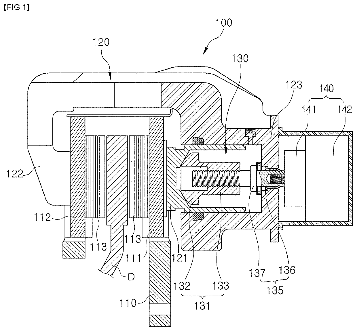
[0028]FIG. 1 is a schematic cross-sectional view of an electronic parking brake applied to an EPB system according to an embodiment of the present disclosure.

[0029]Referring to FIG. 1, an electronic parking brake 100 may include a carrier 110 on which a pair...


PUM


Abstract

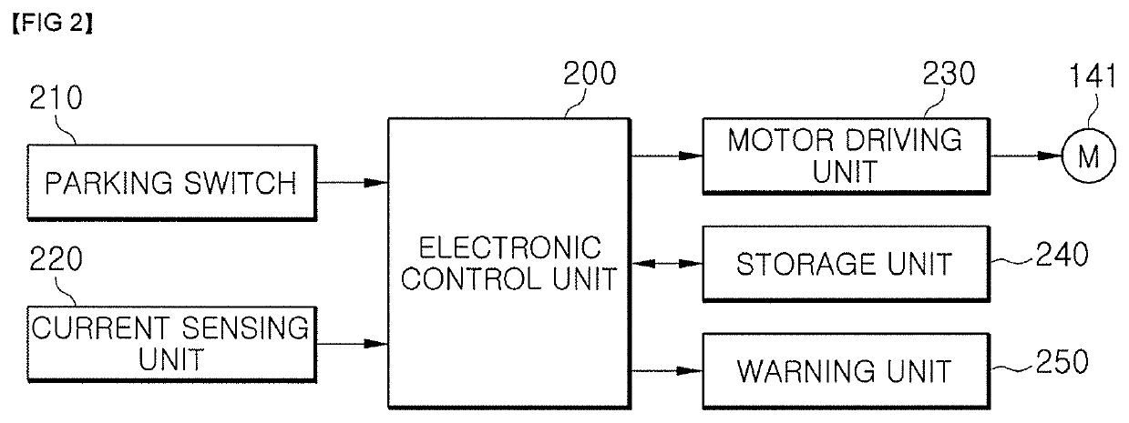
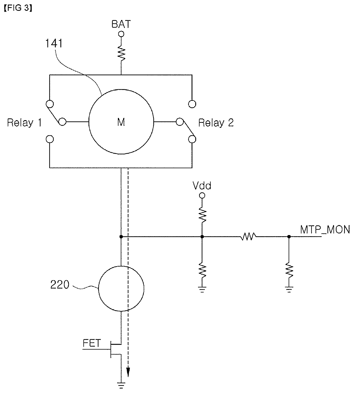
Disclosed are an electronic parking brake system and a control method thereof. The electronic parking brake system according to an embodiment of the present disclosure which comprises an EPB (Electronic Parking Brake) actuator operated by an electric motor, comprises a motor driving unit for driving the electric motor of the EPB actuator, a current sensing unit for sensing a current flowing in the electric motor, and an electronic control unit for accumulating an electric charge amount put into the electric motor from the time when a motor current change rate is higher than a preset change rate if the motor current change rate according to the motor current sensed through the current sensing unit during a parking operation is higher than the preset change rate and determining a stuck failure of the electric motor based on the accumulated electric charge amount.

Description

CROSS-REFERENCE TO RELATED APPLICATION(S)[0001]This application claims the benefit of Korean Patent Application No. 2016-0135011, filed on Oct. 18, 2016 in the Korean Intellectual Property Office, the disclosure of which is incorporated herein by reference.BACKGROUND1. Field[0002]The present disclosure relates to an electronic parking brake system and a control method thereof, and more particularly to an electronic parking brake system and a control method thereof for controlling the activation or deactivation of an electronic parking brake.2. Description of the Related Art[0003]Recently, an electronic parking brake (EPB) system for electronically controlling the driving of a parking brake is used, which is mounted on a normal disk brake to perform a parking brake function.[0004]The electronic parking brake system allows the parking brake to be automatically activated or deactivated according to the control determination of an electronic control unit performing a simple switch opera...

Claims


Application Information

Patent Timeline
Patent Type & Authority Patents(United States)
IPC IPC(8): B60T17/22B60T13/74F16D65/18F16D55/226F16D125/40F16D121/24
CPCB60T17/221B60T13/741F16D55/226F16D65/18F16D65/183B60T2270/406F16D2121/24F16D2125/40B60T13/74B60T17/22B60T8/88B60T8/171B60Y2400/3084B60Y2306/15
Inventor CHOE, JIN YEONG
Owner HL MANDO CORP
Learn More