
Method and system for determining the sid and the thickness of a patient in a radiographic system

a radiographic system and thickness technology, applied in the field of sid measurement, can solve the problems of difficult determination of the exact position and orientation of the image detector relative to the x-ray source, difficult to directly determine the thickness of the patient, and less obvious to accurately determine the acquisition geometry. accurate and reliable results

Active Publication Date: 2020-04-09
AGFA NV
View PDF0 Cites 3 Cited by
  • Summary
  • Abstract
  • Description
  • Claims
  • Application Information

AI Technical Summary

Benefits of technology

This patent aims to provide a system that can accurately and reliably determine the thickness of a patient when positioned against the surface of an imaging detector in a radiography system. This allows for various practical applications, such as automated and accurate determination of the SID for selecting exposure settings and automatic determination of the acquisition geometry of a radiography system in tomosynthesis context for accurate image reconstruction.

Problems solved by technology

It has been a longstanding problem in conventional radiography to be able to accurately determine the optimal exposure settings for a selected exam, given that the age and gender of a patient are known.
It is clear that under these circumstances it is a lot less obvious to accurately determine the acquisition geometry when the relative position information between the different components, such as the X-ray source and the image detector, is not available.
Especially, the determination of the exact position and orientation of an image detector relative to the X-ray source is challenging since the two objects typically do not have a mechanical relationship, and may even not be in a line of sight of each other.
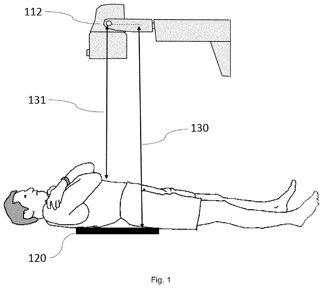
Also, the thickness of the patient cannot be directly derived from easy measurements, as it requires at least the determination of the relative position of the image detector and with respect to the incidence point of the X-ray beam into the patient.
Therefore, distance-measuring techniques that require a clear line of sight cannot be applied.
These solutions require complex calculations of the recorded movements and are not sufficiently accurate for the application described here as the sensor may drift over time.
Additionally, the type of kinetic sensors used in this kind of application have certain intrinsic limitations that do not allow certain parameters to be measured.
For instance, acceleration sensors are not able to detect a rotation of an object oriented in plane parallel with the ground surface (perpendicular to the force of gravity).
This solution is however not very accurate, and is very susceptible to external influences which may influence the magnetic field such as the presence of metallic objects or the presence of other static or non-static magnetic fields, such as the earth's magnetic field or the presence of electromagnets or coils in the vicinity of the detectors.
The technique is thus an improvement over the previously mentioned solution in that it is less susceptible to external magnetic disturbances, but at the same time, it is clear that the technique does not intend (and does not achieve) to obtain absolute location measurements of the sensors attached to the detector.
Today, it is however generally known that the accuracy of the (civil) GPS is insufficient for this intended application of locating an object on the sub-centimeter level, as the standard horizontal accuracy of a civil GPS receiver under optimal signal receiving conditions is 3.5 meters.
Especially when it is generally known that many external factors can degrade the GPS positioning accuracy (such as signal blockage in buildings, or signal reflections against walls), it is clear that the accuracy of the proposed system will especially suffer under the operating conditions of such an X-ray imaging detector alignment system; namely inside a hospital building.
The most promising techniques evading the direct-line-of-sight limitation are based on magnetic field measurement techniques, but so far, only estimations or relative measurements with limited accuracy and reliability have been achieved.

Method used


Image

  • Method and system for determining the sid and the thickness of a patient in a radiographic system
  • Method and system for determining the sid and the thickness of a patient in a radiographic system
  • Method and system for determining the sid and the thickness of a patient in a radiographic system

Examples


Embodiment Construction

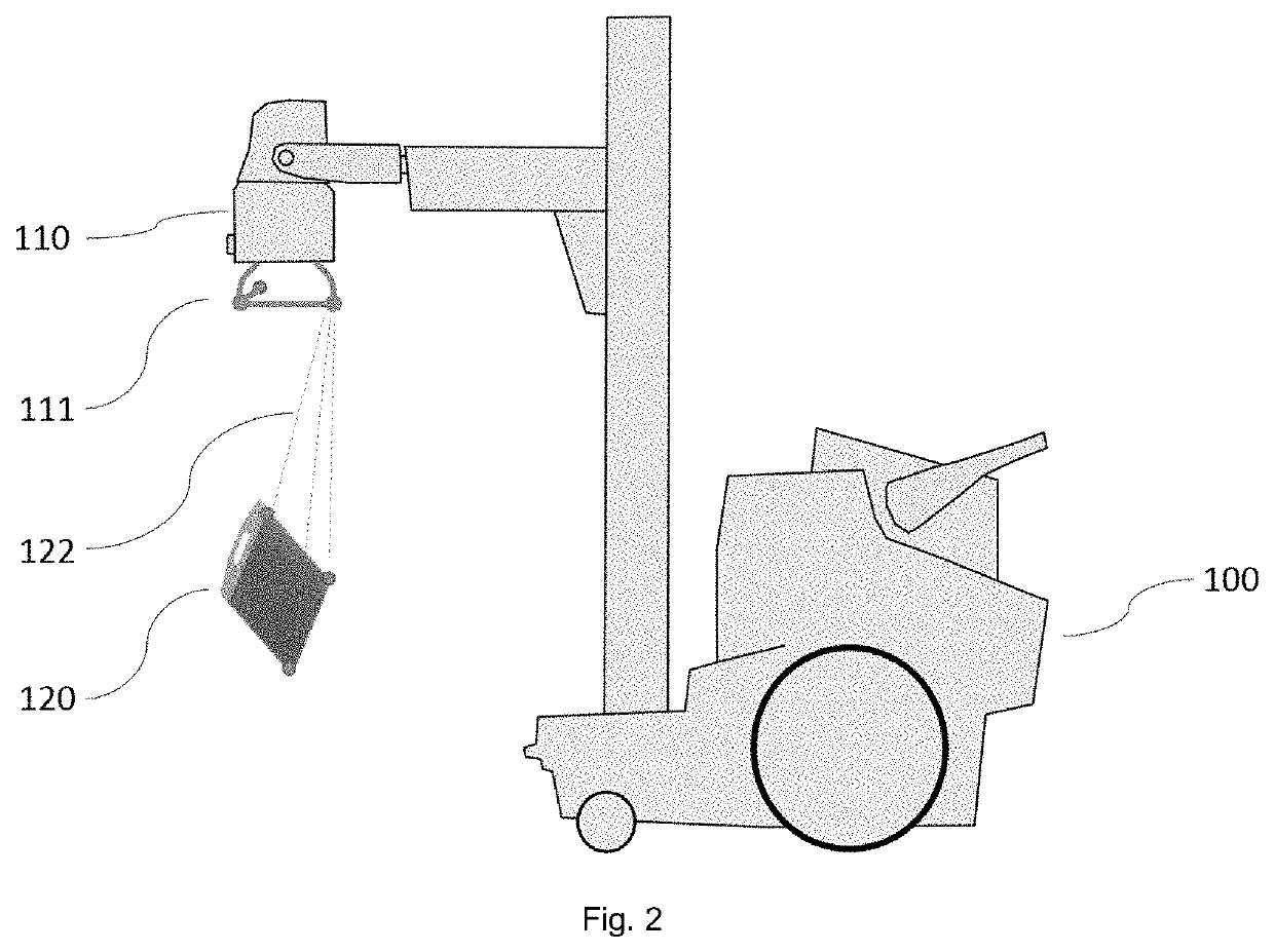
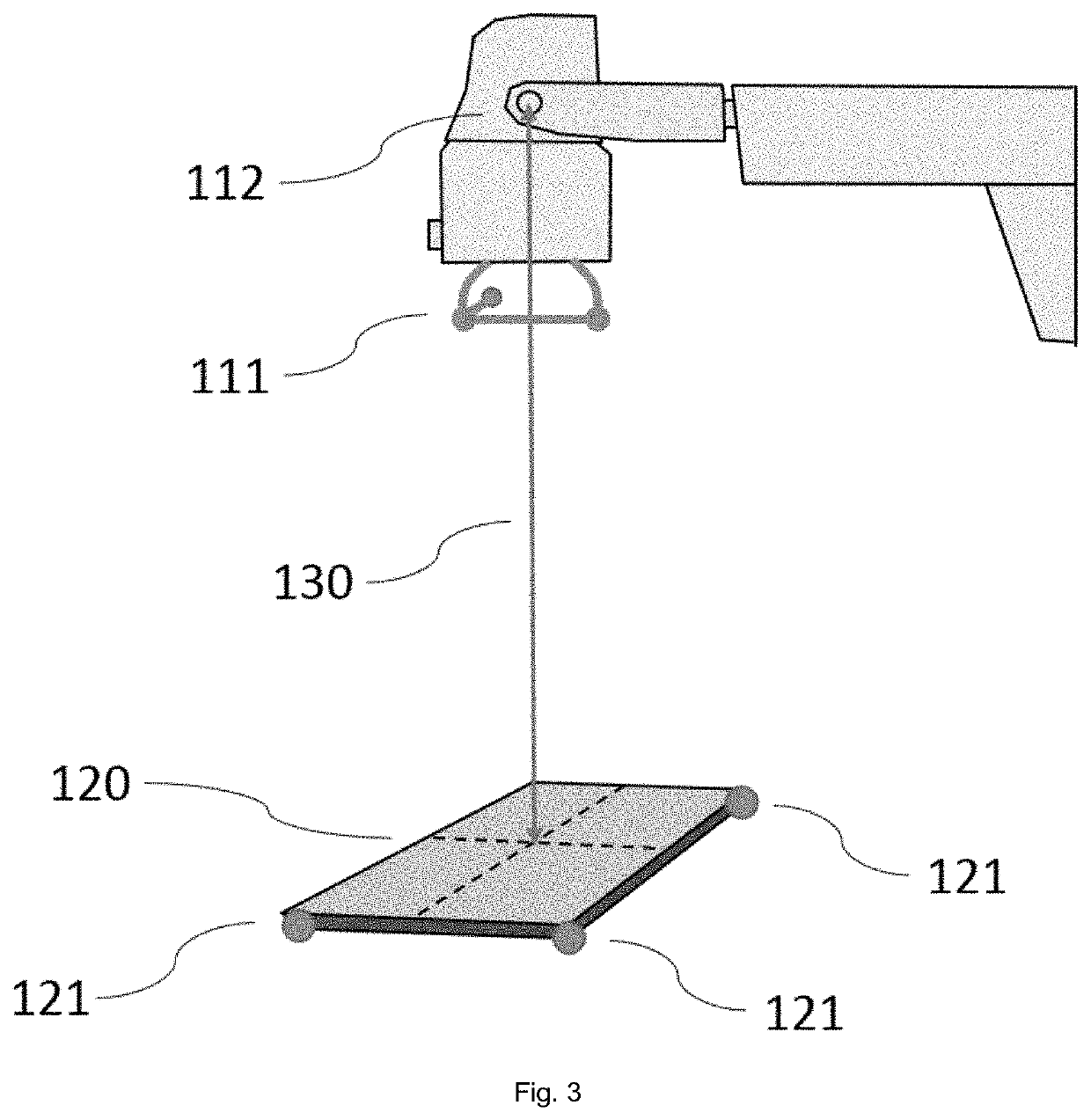
[0027]A first embodiment of this invention is based on the use of a set of at least three signal generators, which are physically connected to an X-ray source assembly of a radiography system. The at least three signal generators are mechanically fixed to the X-ray source assembly in order to fix a reference coordinate system in space which is selected as the point from where the X-ray radiation originates and that determines the orientation of the X-ray beam. This virtual point is called the emission point of the X-ray source. At least three signal generators are required to determine the location and orientation of the reference coordinate system. Adding more signal generator elements may contribute to a better accuracy of the system, but is strictly speaking not required. The at least three signal generators are so arranged that they are spatially separated from each other (for instance located at positions around the X-ray source assembly) so to ensure that their generated signa...


PUM


Abstract

A method and system for accurately determining the SID (source-image-distance) in a radiography configuration with a wireless radiographic detector, and a method and system for determining the thickness of a patient in a radiography configuration. The method for determining the SID is based on a method to accurately determine distances between a set of generator arrays and sensor arrays. The generator arrays and sensor arrays are preferably orthogonally arranged magnetic field generators and sensors that allow measurements of distances without being affected by presence of human tissue between the generator and sensor arrays.

Description

CROSS REFERENCE TO RELATED APPLICATIONS[0001]This application is a 371 National Stage Application of PCT / EP2017 / 062277, filed May 22, 2017. This application claims the benefit of European Application No. 17165497.3, filed Apr. 7, 2017, which is incorporated by reference herein in its entirety.BACKGROUND OF THE INVENTION1. Field of the Invention[0002]The invention generally relates to the measurement of the SID (source-image-distance) and the thickness of a patient for setting the exposure parameters in a conventional radiography configuration, wherein the radiography detector is positioned against one side of the patient, but the detector surface is obscured by the patient when seen from the viewpoint of the X-ray source position.2. Description of the Related Art[0003]It has been a longstanding problem in conventional radiography to be able to accurately determine the optimal exposure settings for a selected exam, given that the age and gender of a patient are known. In order to be ...

Claims


Application Information

Patent Timeline
IPC IPC(8): A61B6/00
CPCA61B6/588A61B6/4452A61B2562/0223A61B6/4405A61B6/587A61B6/547
Inventor NEBOSIS, RAINERCIONA, MICHAEL TED
Owner AGFA NV
Learn More