Method For Monitoring The Thermomechanical Behaviour Of A Subsea Pipe For Transporting Pressurised Fluids

Active Publication Date: 2019-01-31
SOCOTEC MONITORING FRANCE +1
View PDF0 Cites 6 Cited by
  • Summary
  • Abstract
  • Description
  • Claims
  • Application Information

AI Technical Summary

Benefits of technology

The monitoring method described in this patent allows for accurate knowledge of the state of an undersea pipe at the connections between different unit pipe elements. The method involves measuring the mechanical and thermal signatures of each unit pipe element while it is being subjected to various stresses and heating powers. The results can be used to calculate the stiffness matrix and thermal transfer function of each unit pipe element. This information can then be used to detect and locate noise variations inside the pipe, which can indicate the presence of damaging fluid phases or potential damage to the pipe. The monitoring method can also help improve the guidance of external programmed interventions on the pipe and enable better correlation of external view with the acoustic view inside the pipe.

Problems solved by technology

Furthermore, undersea pipes are subjected to high levels of mechanical stress, both while they are being laid on the bottom of the sea via a J-lay tower, which gives rise to high levels of deformation (in particular in bending) in each of the quad-joints of the pipe, and also during the production stage (internal thermal stresses and stresses due to external forces).
Furthermore, it often happens that the sea bottom on which the pipe is resting moves, which gives rise to movements of the pipe, and thus to stresses in them.
), run the risk of leading to major damage or even breakage of the pipes.

Method used


Image

  • Method For Monitoring The Thermomechanical Behaviour Of A Subsea Pipe For Transporting Pressurised Fluids
  • Method For Monitoring The Thermomechanical Behaviour Of A Subsea Pipe For Transporting Pressurised Fluids

Examples


Embodiment Construction

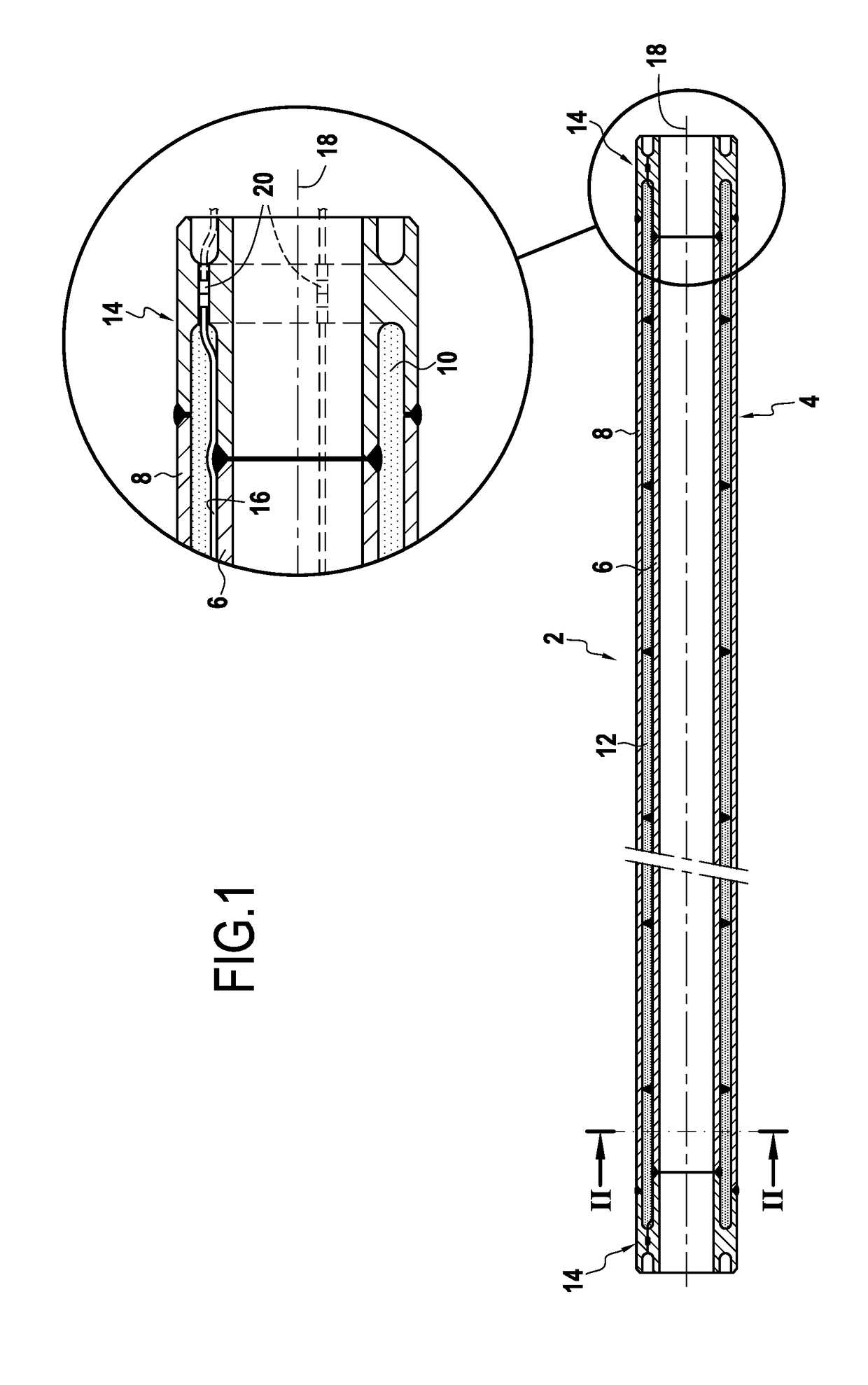
[0036]The invention applies to any undersea pipe resting on the sea bottom and serving to transport specifically oil and gas between undersea hydrocarbon production wells and a surface installation, such as the undersea pipe 2 shown in FIGS. 1 and 2.

[0037]The undersea pipe 2 shown in the figures is typically assembled on land as a plurality of pipe sections 4 each having a unit length of about 10 m to 100 m, depending on the load-holding capacity of the laying system. The term “joints” is also used, in particular “double joints” for two unit pipe elements assembled together, “triple joints” for three unit pipe elements assembled together, “quadruple joints” for four unit pipe elements assembled together, etc. In the description below, the term “quad-joint” is used generically to designate any unit pipe element 4. During laying, the quad-joints 4 are connected to one another on board the ship progressively as they are being laid at sea.

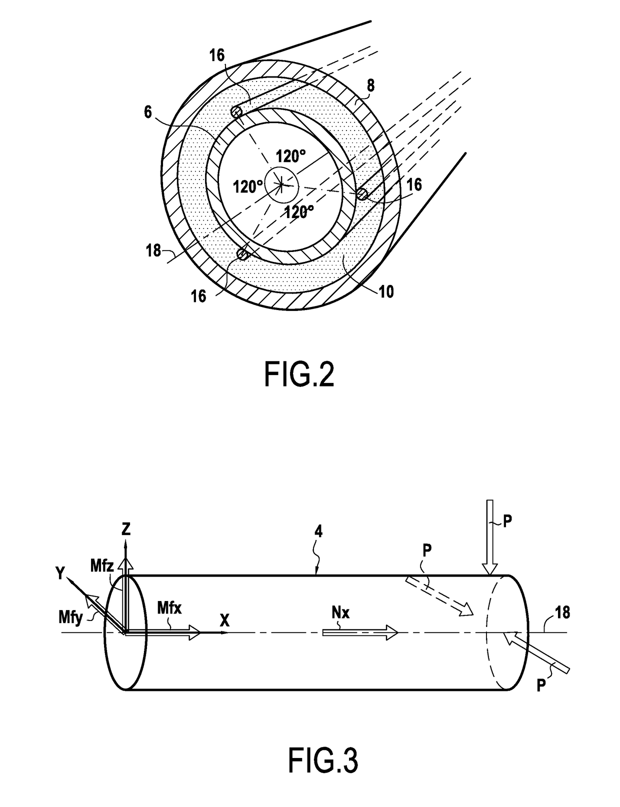
[0038]Furthermore, the undersea pipe 2 is a coax...


PUM


Abstract

A method of monitoring thermomechanical behavior of an undersea pipe (2) transporting fluid under pressure and made by assembling unit pipe elements (4), comprising determining a mechanical signature specific to each unit pipe element, using a measurement cable (16) having an optical fiber sensor using Brillouin backscattering to measure deformation of the pipe element while it is subjected on land to various mechanical stresses in predetermined directions and magnitudes, and establishing a stiffness matrix associated with the mechanical signature of each pipe element, a step of determining a thermal signature specific to each unit pipe element, which step consists in measuring the temperature changes of the unit pipe element while it is being subjected on land to various different electrical heating powers, and in establishing a thermal transfer function associated with the thermal signature of each pipe element, and a monitoring step consisting of recovering.

Description

BACKGROUND OF THE INVENTION[0001]The present invention relates to the general field of undersea fluid transport pipes that rest on the sea bottom or that provide a bottom-to-surface connection for transporting hydrocarbons, e.g. oil and gas, from undersea production wells.[0002]Undersea fluid transport pipes are commonly used in offshore hydrocarbon production. Thus, in an offshore production field, a plurality of wells are generally worked, which wells may be spaced apart from one another by several kilometers, or indeed tens of kilometers. The fluids coming from the various wells need to be collected by pipes that are laid on the sea bottom and transferred by bottom-to-surface connection pipes from an undersea pipe resting on the sea bottom to a surface installation that receives them, e.g. on board a ship or at a collection point situated onshore.[0003]There exist various types of undersea pipes that are used for transporting fluids. The invention relates more particularly to coa...

Claims


Application Information

Patent Timeline
IPC IPC(8): G01D5/353G01H9/00G01K11/32E21B41/00
CPCG01D5/35364G01H9/004G01K11/32E21B41/0007G01K2011/322G01K2011/324G01N25/18E21B17/01G01D5/353E21B47/007G01K11/322G01K11/324
Inventor PIONETTI, FRANCOIS-REGISAGOUMI, JALILSUNDERMANN, AXELMARAVAL, DAMIENLAMOUR, VINCENT
Owner SOCOTEC MONITORING FRANCE
Why Eureka
Try Eureka