Screen apparatus for vibratory separator

a vibratory separator and vibratory screen technology, applied in the direction of filtration separation, separation process, well accessories, etc., can solve the problems of increasing the wear of mud pumps and other mechanical equipment used for drilling, increasing the cost of shipping, and increasing the weight of mud pumps, so as to facilitate insertion into the opening, maximize the effective or useful surface area of the screen, and repair quick and easy

Inactive Publication Date: 2001-12-04
VARCO I P INC
View PDF169 Cites 84 Cited by
  • Summary
  • Abstract
  • Description
  • Claims
  • Application Information

AI Technical Summary

Benefits of technology

Certain prior art shaker screens have a frame side with an in-turned edge which facilitates hooking of the screen, e.g. to a vibrating basket. In one embodiment of the present invention a strip as described above extending between two frame sides also extends into and becomes this in-turned hooked edge. In another aspect a strip is secured to a portion of a hook. To inhibit or prevent fluid leakage at the hook / strip interface, a steel strip may be welded to a metal hook (or a non-metal strip may be bonded to a metal or non-metal hook). In one aspect typical frame sides are not used and only a series of strips with hook edges support the screening material and provide for its mounting to a shale shaker.
The invention, in certain embodiments, discloses a screen for a vibrating separator or shaker that has increased capacity without an increase in overall dimensions. It furthermore accommodates desirable attributes such as resistance to blinding, repairability and longevity. The screen, substantially horizontal when placed on a separator for operation, is formed from one or more layers of mesh. The one or more layers of mesh are formed into an alternating series of ridges and channels lying substantially within the plane of the screen. The ridges increase the surface area of the screen without increasing the overall dimensions of the screen, thus improving flow capacity. Additionally, particles tend to drop into the channels, leaving the tops of the ridges exposed to fluids for relatively unimpeded flow through the screen that further improves flow rates. Furthermore, the ridges and channels tend to assist in evenly distributing separated particles across the screen. Uneven distribution, due to for example rolling of the screen from side to side when used on offshore platforms, degrades flow capacity of the screen.
In accordance with another aspect of the invention, the ridges and channels of the panel have substantially flat surfaces on which the openings are located. A substantially planar opening allows a flat plug to be inserted into the opening for improved fit and sealing. The plug is preferably formed with an edge that facilitates insertion into opening and into which the edge of the cell opening snugly fits, making a repair quick and easy.
In accordance with another aspect of the invention, the ridges have a generally triangular cross section. In a preferred embodiment, the ridges are formed from two surfaces in a triangular configuration and the channel is formed from a flat bottom surface extending between the ridges. This geometry tends to maximize effective or useful surface area of the screen, especially if flat surfaces are used on the ridge to facilitate repair. During normal operation of the separator or shaker, most of the particles fall into the channel and the material to be separated tends to flow through the screen along the sides of the ridges and the bottom of the channel. A generally triangular configuration of the ridge tends to expose greater screen area to the flow and to minimize the amount of area on top of the ridge that tends not to be exposed to material flow.

Problems solved by technology

If drilled solids are not removed from the mud used during the drilling operation, recirculation of the drilled solids can create weight, viscosity, and gel problems in the mud, as well as increasing wear on mud pumps and other mechanical equipment used for drilling.
The frame of the vibrating screen is resiliently suspended or mounted upon a support and is caused to vibrate by a vibrating mechanism, e.g. an unbalanced weight on a rotating shaft connected to the frame.
Such screens present a variety of problems, deficiencies, and disadvantages, including: decreased flow area due to area occluded by solid parts of the apertured plate; necessity to either purchase relatively expensive apertured plate or provide for in-house perforating of a solid plate; plate weight increases wear on parts such as rubber screen supports or cushions and can inhibit required vibration; large plate surface area requires relatively large amount of bonding means for bonding screens to the plate; and a finished screen which is relatively heavy increases handling problems, hazards, and cost of shipping.
However, screens of bolting cloth tears more easily than market or mill grade screens, especially when used in harsh conditions such as drilling and mining operations.
The smaller diameter wires tend to have less tensile strength and break more easily, and the finer mesh also tends not to retain its shape well.
During vibration, wires separate enough to allow particles of substantially the same size or slightly larger than the openings to fall between the wires and become lodged, thus "blinding" the openings of the screen and reducing capacity of the screen.
If a particle becomes lodged when the wires are at a maximum distance apart, it is almost impossible to dislodge the particle.
Unfortunately, some wire mesh, especially bolting cloth, is tensioned.
However, restricted movement of the wires reduces the probability that, once a near sized particle becomes stuck, the wires will subsequently separate to allow the particle to pass.
Another problem faced in most applications is the tearing of the screen.
The problem can be especially acute in heavy duty applications such as drilling and mining.
Unfortunately, bonding the screen to the support panel further restricts relative movement of the layers and the wires in each mesh layer, thus compounding the problem of blinding.
Blinding and tearing of the screens reduce the capacity of the screen continually through its useful life.
Although capacity can be increased by increasing the total area the screens, the size of the screen is limited in most applications, such as on drilling rigs, especially those on offshore platforms.

Method used


Image

  • Screen apparatus for vibratory separator
  • Screen apparatus for vibratory separator
  • Screen apparatus for vibratory separator

Examples


Embodiment Construction

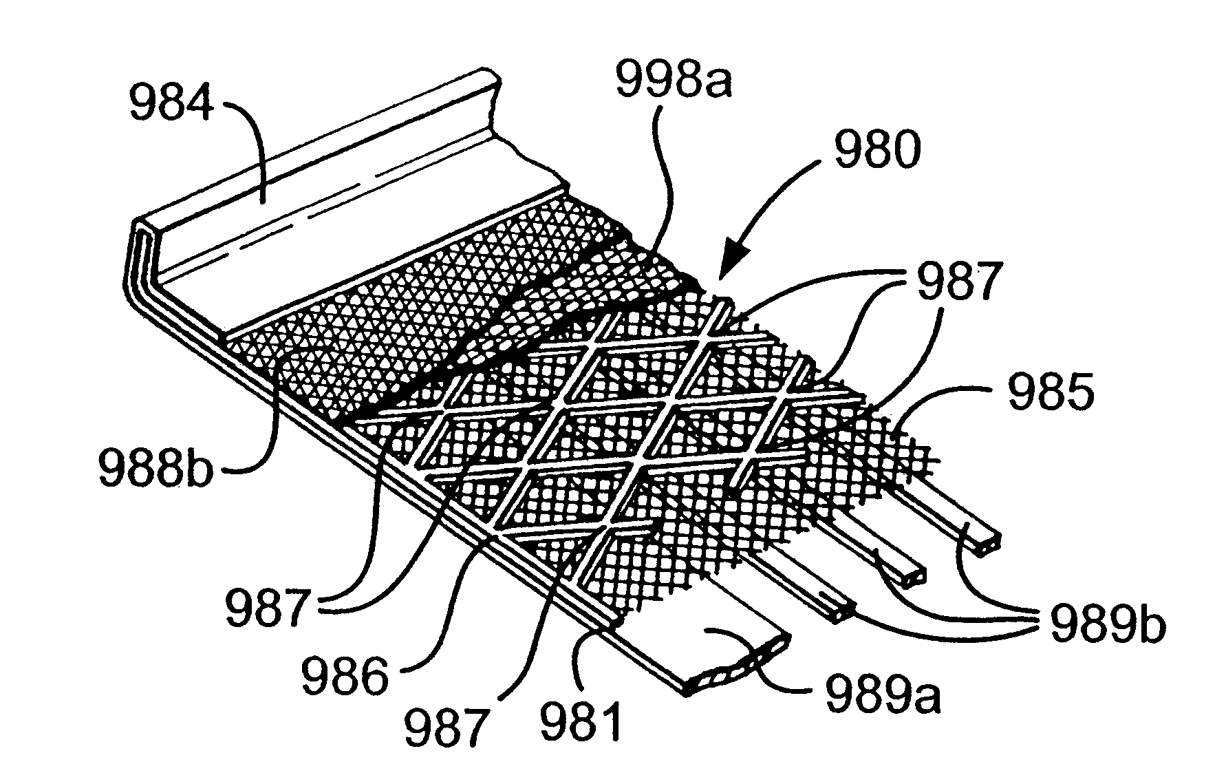
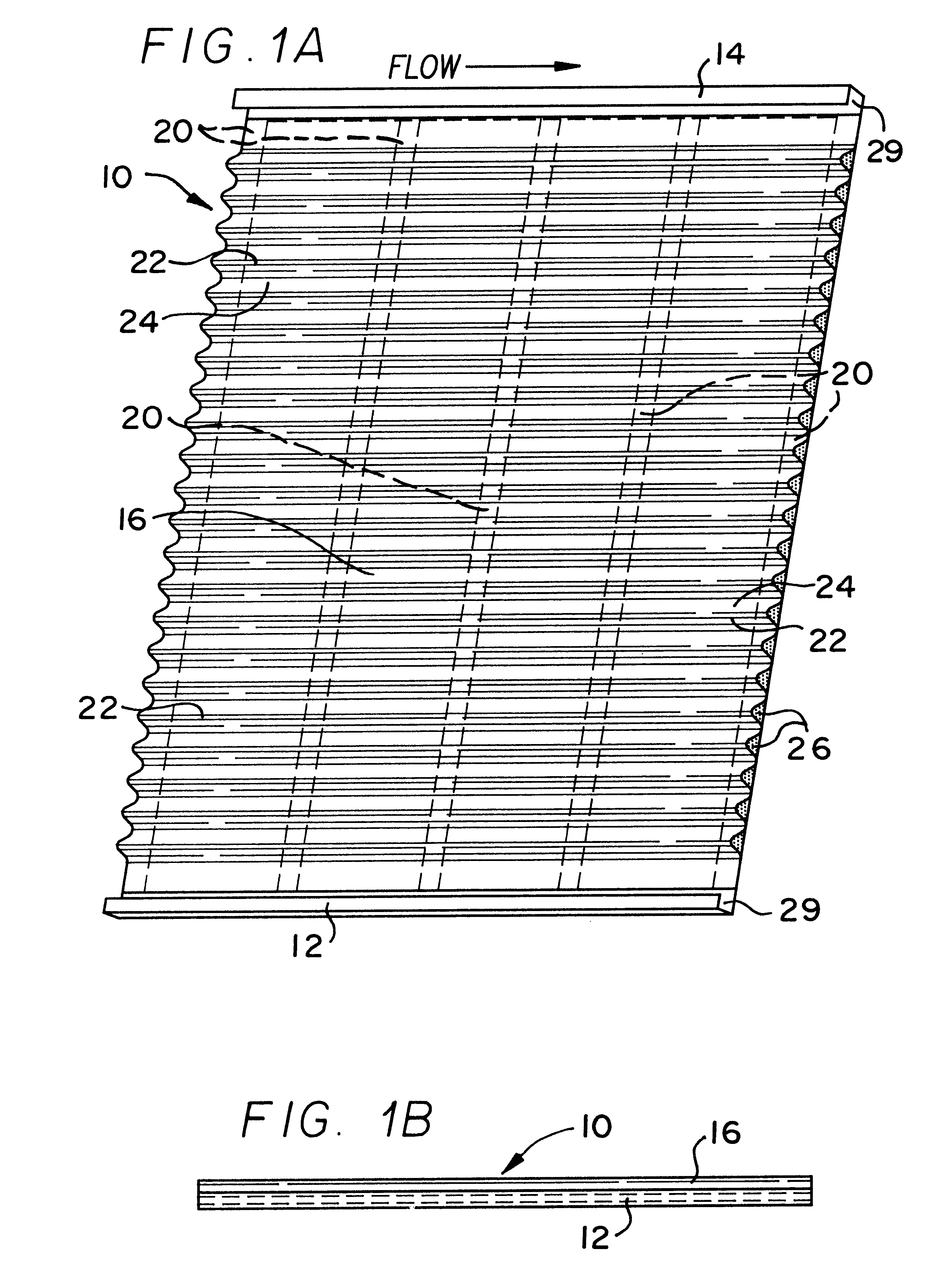
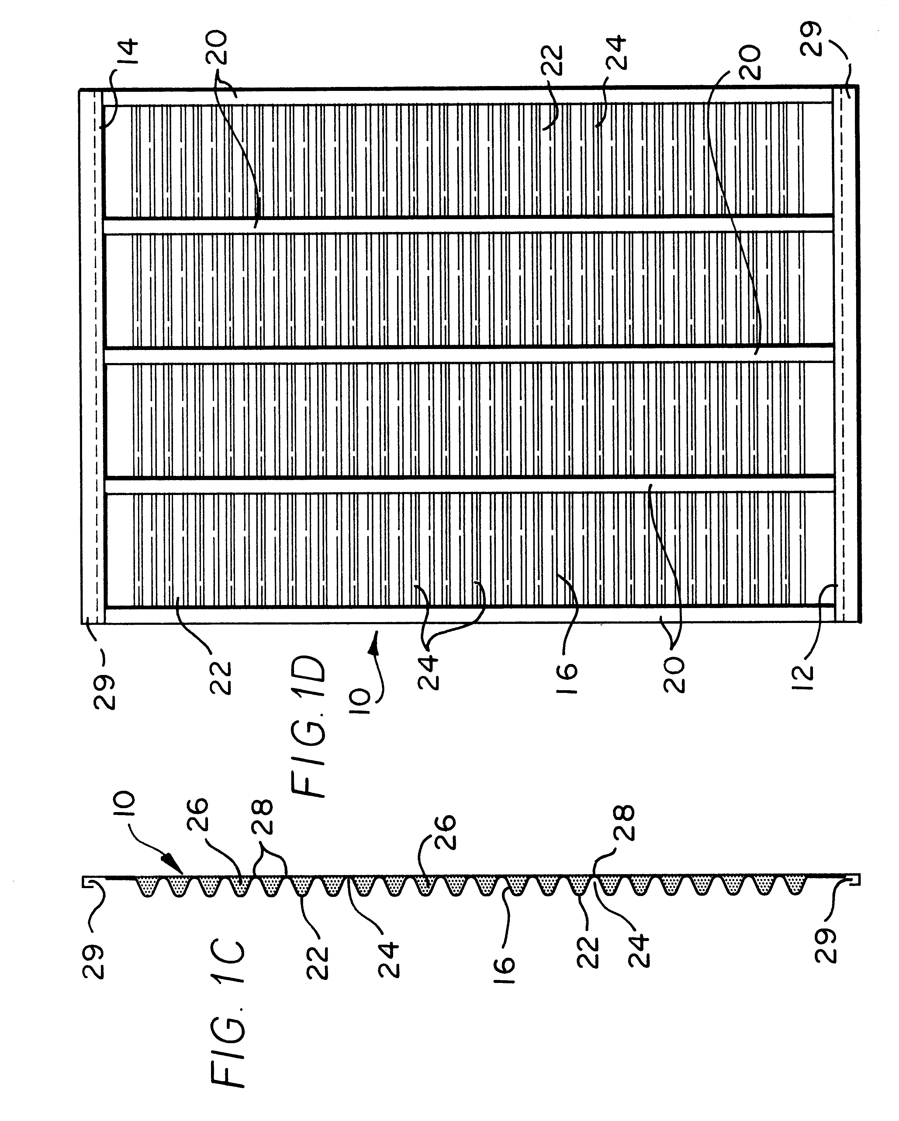
FIG. 1A shows a screen 10 according to the present invention with a frame with two sides 12 and 14 with strips 20 extending between the two sides 12 and 14; and screen material 16 on the strips 20 and connected to the sides 12 and 14. Screen material 16 (and any other screen or screening material disclosed herein) represents any known mesh, screen, or screens, used in any combination, bonded together or unbonded. The screen material 16 as shown is "three-dimensional," i.e., not generally flat and has undulating portions with hills 22 (as seen in FIGS. 1A-1C) and valleys 24. (It is within the scope of this invention for the screening material 16 and any other screening material herein to be generally flat.)

Plugs 26 may plug ends of the hills 22. Incorporated fully herein by reference is the disclosure of co-owned pending U.S. Application Ser. No. 08 / 282,983 filed on Jul. 29, 1994 entitled "Shale Shaker Screens" which discloses three-dimensional screens with plugged ends.

In the screen...


PUM

PropertyMeasurementUnit
widthaaaaaaaaaa
thickaaaaaaaaaa
thickaaaaaaaaaa

Abstract

A screen assembly for a vibratory separator, the screen assembly including at least one lower coarse screen member, at least one upper fine screen member above the at least one lower coarse screen member and fused with plastic to the at least one lower coarse screen member, and a strip member beneath and adhered to the at least one lower coarse screen member. In one aspect the strip member includes two side strips, two end pieces, and a plurality of spaced-apart strips parallel to the two side strips each with an end terminating at, in, or on each of the end pieces.

Description

1. Field Of The InventionThe present invention is directed to vibratory screens, to filtering screens, to such screens that are generally flat or that are not flat, to devices with such screens, and to shale shakers with such screens, and to shakers for separating particles.2. Description of Related ArtThe need for solids control in drilling mud used in hydrocarbon well drilling is well known in the prior art. Drilling mud, typically a mixture of clay and water and various additives, is pumped down through a hollow drill string (pipe, drill collar, bit, etc.) into a well being drilled and exits through holes in a drillbit. The mud picks up cuttings (rock) and other solids from the well and carries them upwardly away from the bit and out of the well in a space between the well walls and the drill string. At the top of the well, the solids-laden mud is discharged over a shale shaker, a device which typically has a series of screens arranged in tiered or flat disposition with respect t...

Claims


Application Information

Patent Timeline
Patent Type & Authority Patents(United States)
IPC IPC(8): B01D29/07B01D29/01B01D33/03B01D33/00B01D33/01B07B1/48B07B1/46E21B21/06E21B21/00
CPCB01D29/012B01D29/07B01D33/0093B01D33/0183B01D33/0376B01D33/0384B07B1/46B07B1/4618B07B1/4627B07B1/4645B07B1/4654B07B1/4663B07B1/4672B07B1/469B07B1/48E21B21/06E21B21/065B01D33/41B01D29/52B01D29/72B01D29/445B01D33/0191B01D2201/0415B01D2201/188B07B2201/04
Inventor SEYFFERT, KENNETH W.ADAMS, THOMAS C.LARGENT, DAVIDSCHULTE, JR., DAVID L.GRICHAR, CHARLES N.LEONE, VINCENT D.WALKER, JEFFREYMCCLUNG, III, GUY L.
Owner VARCO I P INC
Why Eureka
Try Eureka