Pressure adjustment apparatus and image forming apparatus, and pressure adjustment method and liquid remaining amount determination method

a technology of pressure adjustment apparatus and image forming apparatus, which is applied in the direction of printing, other printing apparatus, etc., can solve the problems of affecting the time required for the standby time until the start of printing operations, and affecting the quality of the image formed on the ejection receiving medium, etc., so as to reduce the time required for the pressure in the liquid ejection head to reach a specified negative pressure, the time tim

Inactive Publication Date: 2008-08-21
FUJIFILM CORP
View PDF3 Cites 84 Cited by
  • Summary
  • Abstract
  • Description
  • Claims
  • Application Information

AI Technical Summary

Benefits of technology

[0007]The present invention has been contrived in view of these circumstances, an object thereof being to provide a pressure adjustment apparatus which is able to reduce the pulsating flow generated by a pump that adjusts the back pressure of a liquid ejection head, while also being able to shorten the time required until the pressure inside the liquid ejection head is set to a specified negative pressure, and to provide an image forming apparatus comprising this pressure adjustment apparatus, a pressure adjustment method for adjusting the back pressure in a liquid ejection head, and a remaining amount of liquid determination method which utilizes this pressure adjustment.
[0009]In this aspect of the present invention, it is possible to reduce the pulsating flow generated by the pump which adjusts the back pressure of the liquid ejection head, and to switch between the state where the pump is connected to the gas chamber of the tank without passing via the buffer chamber and the state where the pump is connected to the gas chamber of the tank via the buffer chamber, and therefore it is possible to shorten the time (back pressure start up time) until the back pressure of the liquid ejection head is initialized or reset to a specified negative pressure which is lower than the atmospheric pressure. Consequently, the standby time until the start of a printing operation is shortened, and the printing productivity is improved. Moreover, after setting the negative pressure, it is possible to adjust the pressure of the buffer chamber in a state where the connection between the buffer chamber and the gas chamber of the tank is shut off, and therefore, it is also possible to start a printing operation even during pressure adjustment of the buffer chamber.
[0014]In this aspect of the present invention, it is possible to determine the remaining amount of ink by utilizing the pulsating flow during pressure adjustment (pressure adjustment without the use of the buffer chamber) which is not performed via the buffer chamber, without providing a separate sensor for measuring the remaining amount of ink.
[0016]In this aspect of the present invention, it is possible to determine the remaining amount of ink without providing a separate sensor for measuring the remaining amount of ink, and furthermore it is also possible to improve the accuracy of the determination of the remaining amount of ink, by utilizing both the pulsating flow during pressure adjustment (pressure adjustment without the use of the buffer chamber) which does not pass via the buffer chamber, and the pulsating flow during pressure adjustment (pressure adjustment with the use of the buffer chamber) via the buffer chamber.
[0022]According to the present invention, the pulsating flow (gas flow pulsations) generated from a pump which adjusts the back pressure of a liquid ejection head is reduced, and furthermore, the time required for the pressure in the liquid ejection head to reach a specified negative pressure can be shortened.

Problems solved by technology

Moreover, if the pressure in the flow channels inside the liquid ejection head varies, then this affects the liquid droplet generating process, which in turn affects the quality of the image formed on the ejection receiving medium.
However, since the buffer tank provided in the ink tube between the pump and the liquid ejection head generally has a large volume, then it takes time until the pressure inside the liquid ejection head reaches a prescribed negative pressure which is lower than the atmospheric pressure.
If it takes time to establish the back pressure (a negative pressure which is lower than the atmospheric pressure) in the liquid ejection head in this way, then the standby time until the start of a printing operation becomes longer, and therefore the printing productivity declines.

Method used


Image

  • Pressure adjustment apparatus and image forming apparatus, and pressure adjustment method and liquid remaining amount determination method
  • Pressure adjustment apparatus and image forming apparatus, and pressure adjustment method and liquid remaining amount determination method
  • Pressure adjustment apparatus and image forming apparatus, and pressure adjustment method and liquid remaining amount determination method

Examples


Embodiment Construction

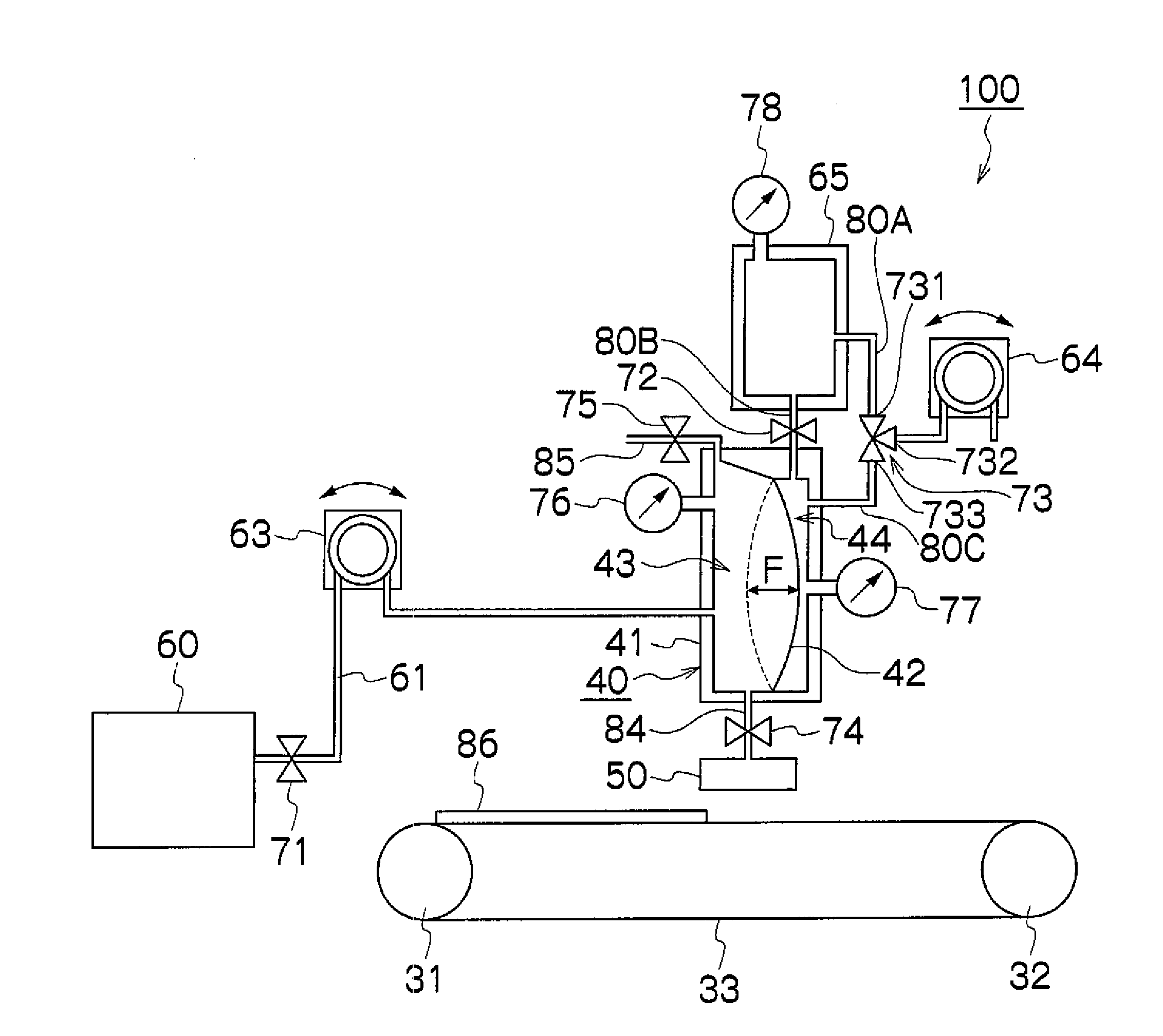
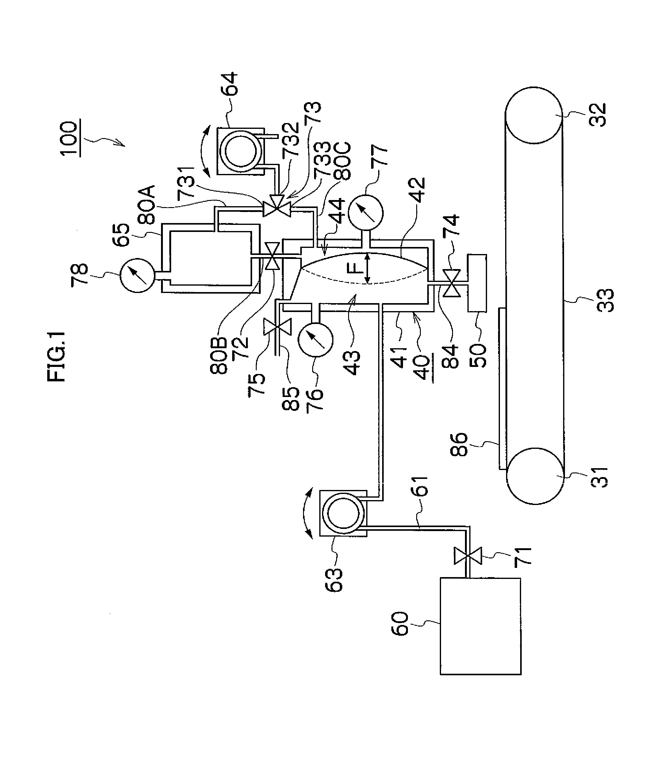
[0038]FIG. 1 is a schematic drawing showing the principal part of an image forming apparatus 100 (liquid droplet ejection apparatus) which is provided with a pressure adjustment apparatus according to an embodiment of the present invention.

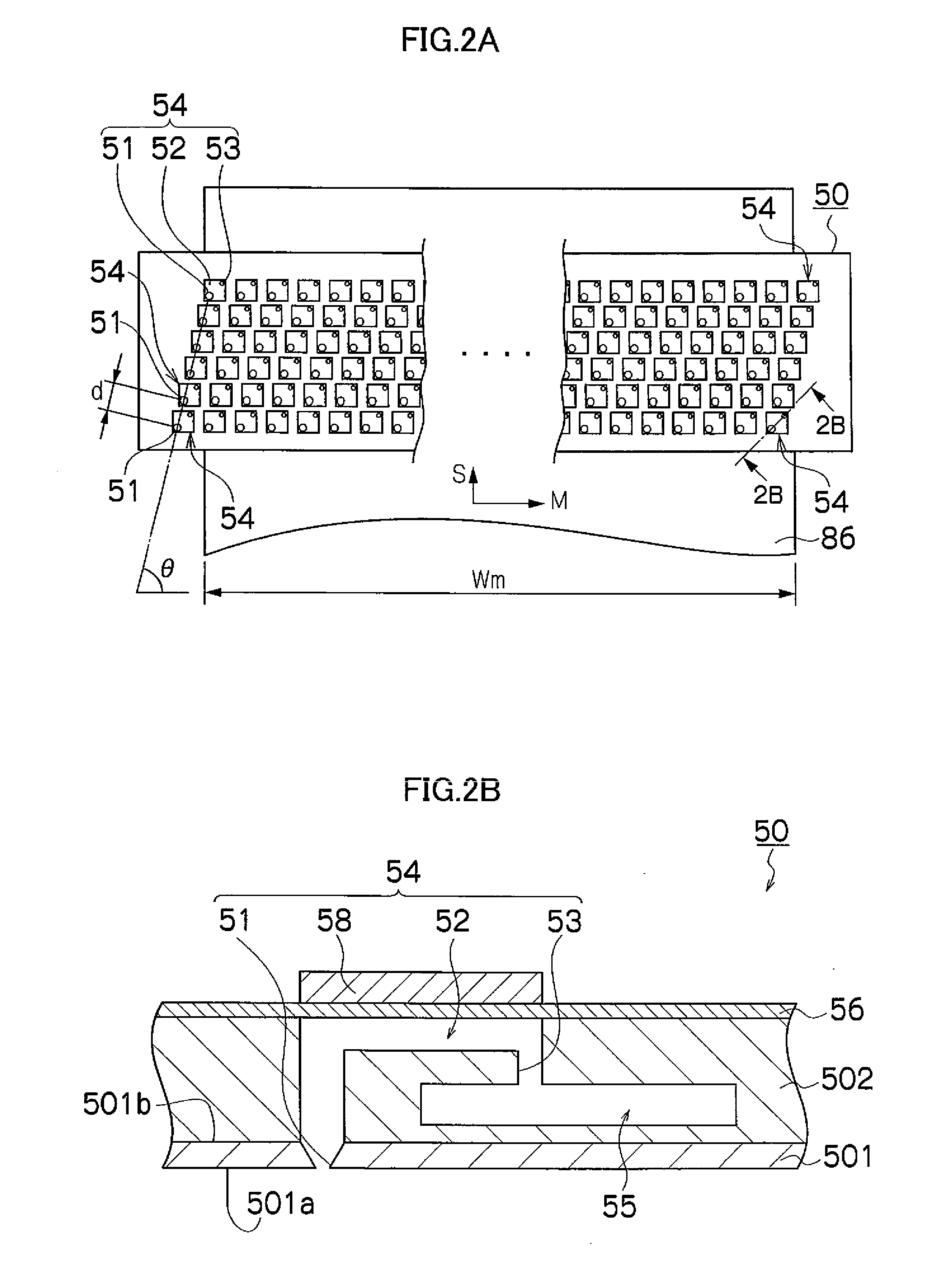
[0039]In FIG. 1, the image forming apparatus 100 comprises a liquid ejection head 50 which ejects ink droplets, conveyance rollers 31 and 32, and a conveyance belt 33 which is set about the conveyance rollers 31 and 32. By ejecting ink droplets from the liquid ejection head 50 towards an ejection receiving medium 86 such as a paper which is conveyed on the conveyance belt 33, an image is formed on the ejection receiving medium 86.

[0040]The image forming apparatus 100 comprises a main tank 60 and a sub tank 40. The ink stored in the main tank 60 is supplied to the sub tank 40 via a first liquid supply flow channel 61 which leads from the main tank 60 to the sub tank 40. The ink stored temporarily in the sub tank 40 is then supplied to the liquid ej...


PUM


Abstract

A pressure adjustment apparatus for adjusting a pressure of liquid inside a liquid ejection head including nozzles and flow channels includes: a tank; a pump; a buffer chamber; a first switching device; and a second switching device. The tank includes a movable film and a hermetically sealed container of a prescribed volume, the movable film dividing the hermetically sealed container into a gas chamber filled with gas and a liquid chamber filled with the liquid to be supplied to the liquid ejection head. The pump changes a pressure of the gas inside the gas chamber so as to adjust a pressure of the liquid inside the liquid chamber. The buffer chamber is filled with the gas and damps gas-flow pulsations caused by the pump. The first switching device connects and disconnects the buffer chamber and the gas chamber. The second switching device switches between a state where the pump is connected to the gas chamber without through the buffer chamber, and a state where the pump is connected to the buffer chamber.

Description

BACKGROUND OF THE INVENTION[0001]1. Field of the Invention[0002]The present invention relates to a pressure adjustment apparatus provided with a buffer chamber for damping a pulsating flow generated by a pump which adjusts the back pressure in a liquid ejection head, and to an image forming apparatus provided with this pressure adjustment apparatus, a pressure adjustment method for adjusting the back pressure in a liquid ejection head, and a liquid remaining amount determination method which is based on the adjustrnent of back pressure in a liquid ejection head.[0003]2. Description of the Related Art[0004]An inkjet printer has been known which includes a plurality of nozzles which eject ink, a plurality of pressure chambers which are connected respectively to the plurality of nozzles, and a common flow channel for supplying ink to the plurality of pressure chambers. In the liquid ejection head of this kind, in order to avoid leakage of ink from the nozzles, it is necessary to set th...

Claims


Application Information

Patent Timeline
Patent Type & Authority Applications(United States)
IPC IPC(8): B41J2/175B41J29/38
CPCB41J2/175B41J2/17566B41J2/17556
Inventor KATADA, MASAHITO
Owner FUJIFILM CORP
Why Eureka
Try Eureka