
Weight-on-gear sensor

a technology of aircraft and sensors, applied in the field of aircraft weight-on-gear sensors, can solve the problems of easy damage of sensors, unreliable systems dependent on physical relationship, complex systems developed to determine, etc., and achieve the effect of accurate and reliable determination of the weight-on-gear status of aircraft and affordable operation

Active Publication Date: 2009-12-29
TEXTRON INNOVATIONS
View PDF7 Cites 8 Cited by
  • Summary
  • Abstract
  • Description
  • Claims
  • Application Information

AI Technical Summary

Benefits of technology

The solution offers accurate and reliable weight-on-gear status indication, operational redundancy, and adaptability to different landing gear configurations, ensuring reliable performance under harsh conditions at a lower operational cost.

Problems solved by technology

Some complex systems have been developed to determine whether an aircraft with opposite landing skids is in the air.
One problem with these systems is that unusually hard landings can deform either the fuselage or the cross tube, making systems that are dependent on this physical relationship unreliable.
The main problem with these systems is that these sensors are easily damaged by harsh environments and therefore not suitable for extended service.
Yet other systems use complex sensors with low tolerances in very limited ranges of operation.
Once the range of operation is exceeded, such as by a hard landing or large swing in temperature, the sensor is not able to reliably track further operation of the aircraft.
As might be expected, the above systems may be very expensive either due to initial cost or the high cost associated with frequent maintenance or replacement.

Method used


Image

  • Weight-on-gear sensor
  • Weight-on-gear sensor
  • Weight-on-gear sensor

Examples


Embodiment Construction

[0024]The present invention represents the discovery that linear motion sensors may be used to accurately determine the weight-on-gear status of an aircraft in a wide range of operational conditions. A weight-on-gear sensor according to the present invention is particularly useful in applications where an aircraft has opposite landing skids connected by a cross tube.

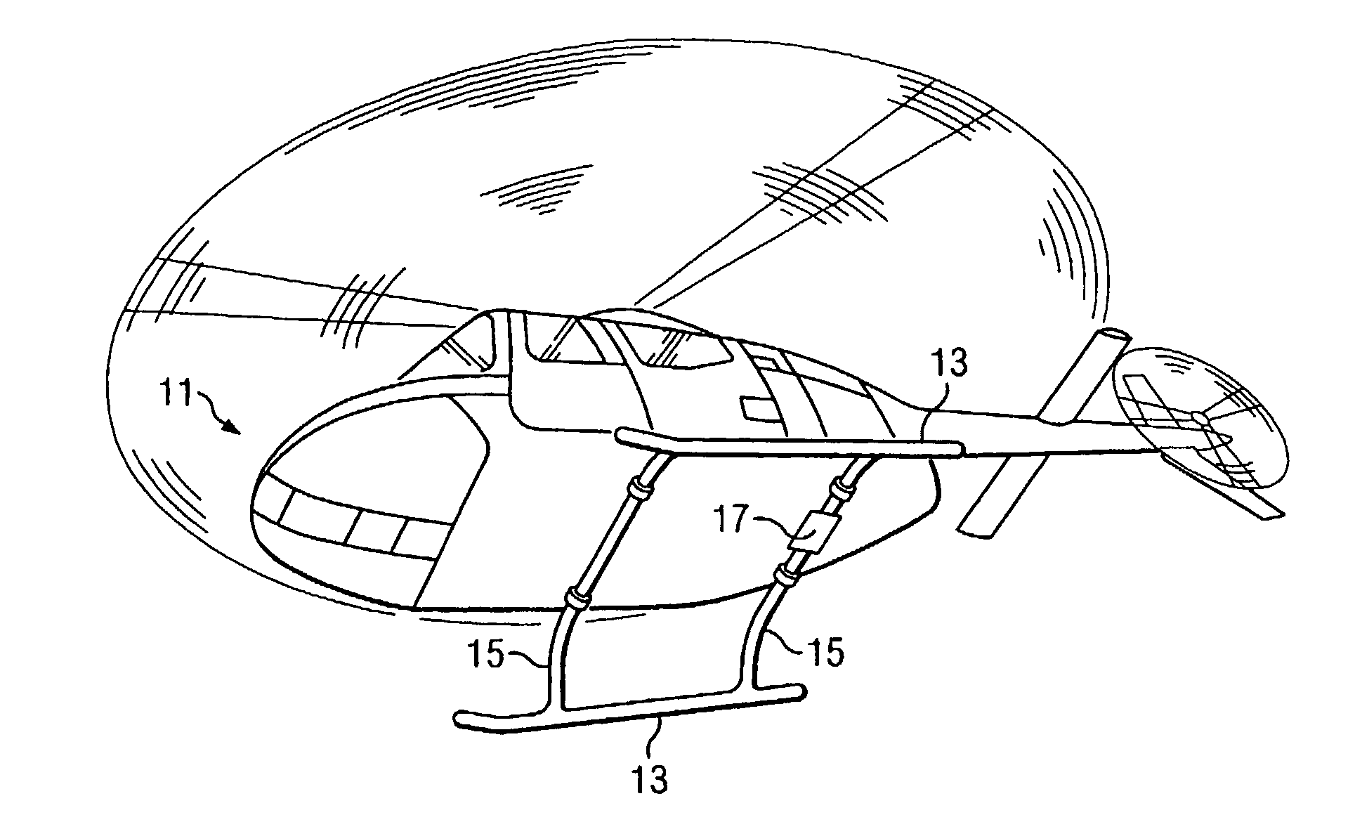
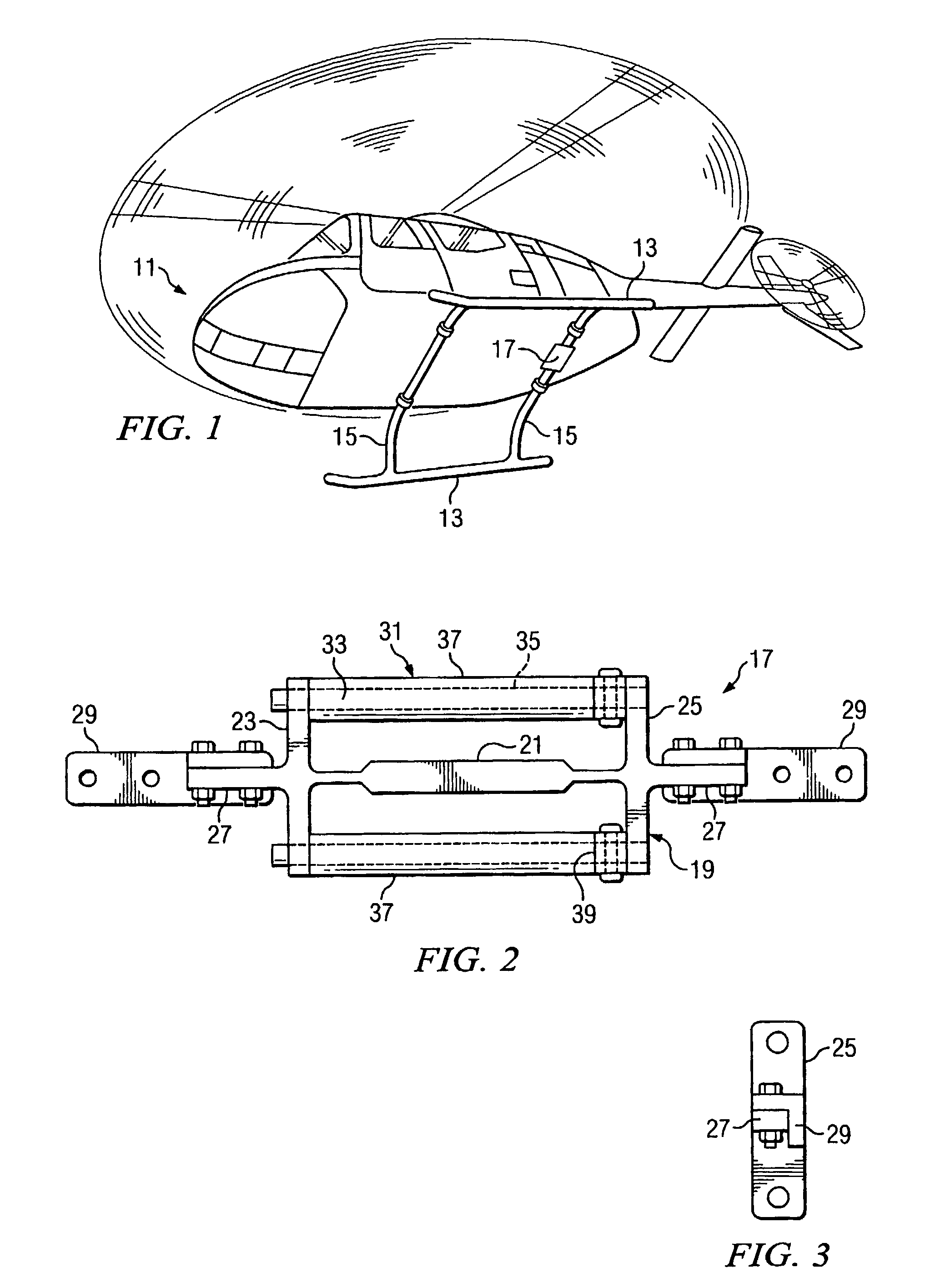
[0025]Referring to FIG. 1 in the drawings, the preferred embodiment of an aircraft 11 with landing skids 13 connected by a cross tube 15 having a weight-on-gear sensor 17 according to the present invention is illustrated. Weight-on-gear sensor 17 provides data to the flight control computer (not shown), or FCC, onboard aircraft 11. The data provided allows the flight control computer to accurately determine the weight-on-gear status of aircraft 11. For example, if the weight-on-gear status is indicated as positive, aircraft 11 is being supported by landing skids 13. Otherwise, if the weight-on-gear status is negative, ai...


PUM


Abstract

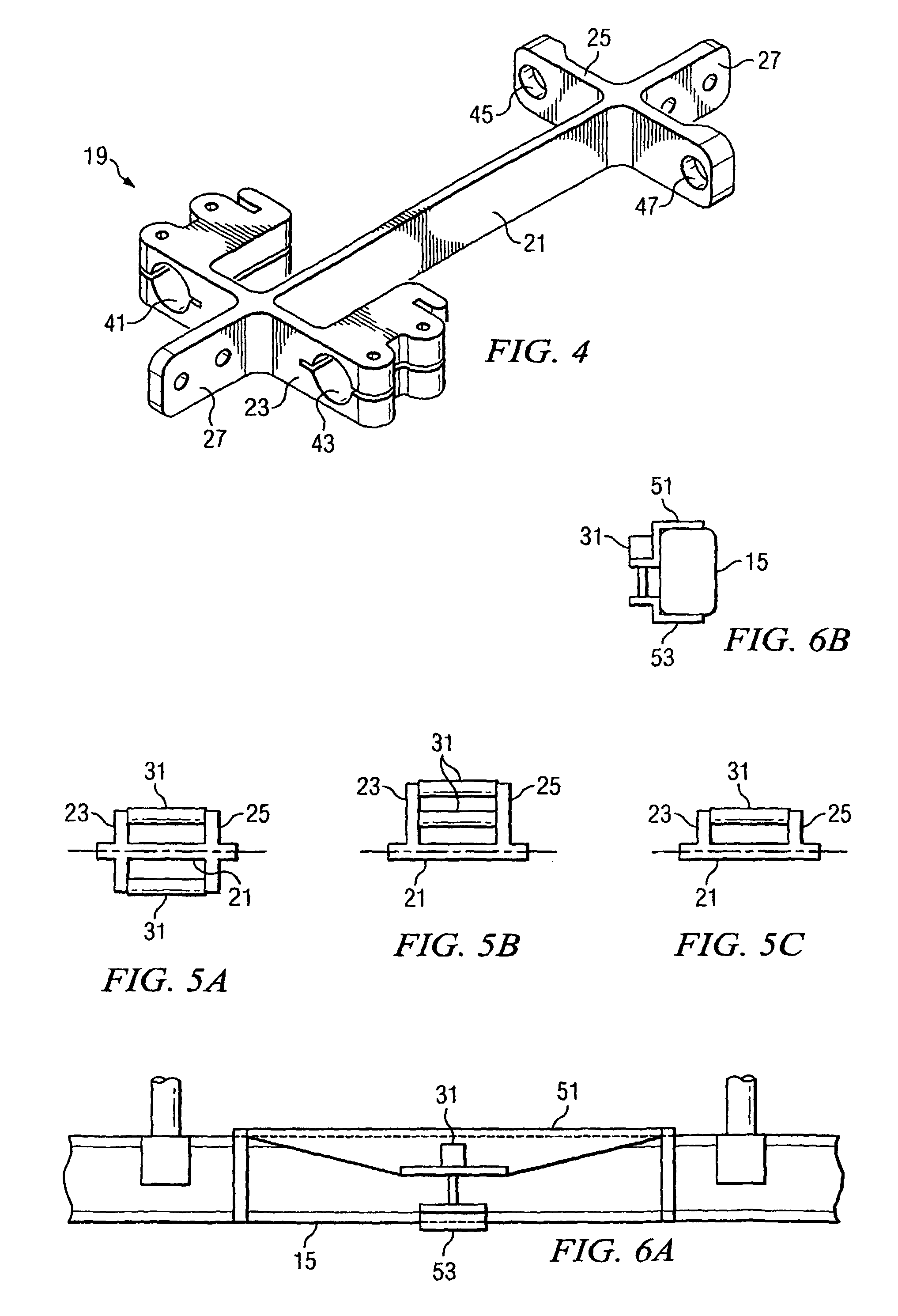
A weight-on-gear sensor for use on an aircraft with landing skids having a bracket and a displacement sensor attached to the bracket is disclosed. The bracket has a center member connecting a first end member to a second end member. The center member has a centerline and the end members extend from the centerline of the center member. Mounting members extend along the centerline of the center member to facilitate attachment of the bracket to a cross tube. The displacement sensor connects the first end member to the second end member. The displacement sensor is parallel to, and offset from, the centerline of the center member so that when a bending moment is applied to the center member the first displacement sensor is either elongated or shortened.

Description

GOVERNMENT LICENSE RIGHTS[0001]The U.S. Government has a paid-up license in this invention and the right in limited circumstances to require the patent owner to license others on reasonable terms as provided for by the terms of Contract No. N00019-96-C-0128 awarded by NAVAIR.TECHNICAL FIELD[0002]The present invention relates to sensors for aircraft. In particular, the present invention relates to weight-on-gear sensors for aircraft with landing skids.DESCRIPTION OF THE PRIOR ART[0003]For a multitude of reasons it is important for various aircraft systems to know if the aircraft is on the ground or in the air. This is referred to in this application as “weight-on-gear” status. For the purposes of this application, “positive” weight-on-gear status means that the aircraft has landed on a surface, and “negative” weight-on-gear status means that the aircraft is airborne. One reason this is important is the desire to disable, or adjust, the operation of weapons systems, or other systems, ...

Claims


Application Information

Patent Timeline
Patent Type & Authority Patents(United States)
IPC IPC(8): B64C25/52
CPCB64C25/001B64C25/52B64C2025/325
Inventor MAST, JAMES GRANTCOVINGTON, CHARLES ERICDARDEN, PAUL EUGENEMCKEOWN, WILLIAM L.
Owner TEXTRON INNOVATIONS
Learn More