
Position learning system for electric shift-by-wire system

a technology of electric shift and learning system, which is applied in the direction of gearing control, gearing element, belt/chain/gearing, etc., can solve the problems of difficult hard to recognize the accurate position of the motor, and difficult to recognize the position of the motor in a simple and accurate manner

Active Publication Date: 2021-04-13
HYUNDAI KEFICO CORP
View PDF17 Cites 0 Cited by
  • Summary
  • Abstract
  • Description
  • Claims
  • Application Information

AI Technical Summary

Benefits of technology

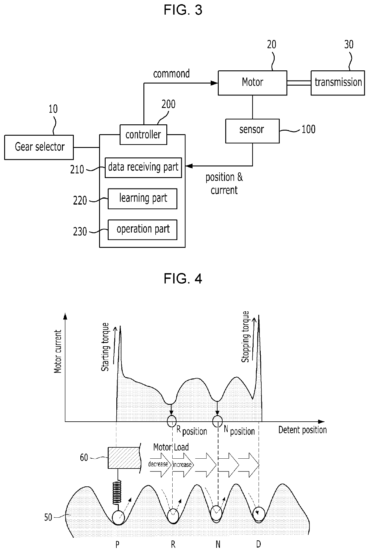
[0012]To accomplish the above-mentioned object, according to one aspect of the present invention, there is provided a position learning system for an electric shift-by-wire system, which senses changes in the load of a motor according to operations of a four-stage detent plate and a detent spring to learn positions of shift stages of the electric shift-by-wire system, the position learning system including: a sensor for sensing the current generated from the motor; and a controller for receiving current data until a shift stage P is switched to a shift stage D or the shift stage D is switched to the shift stage P from the sensor, learning positions of shift stages R and N through the received current data, and performing offset operations on the basis of the learned positions of the shift stages R and N to learn positions of the shift stages P and D.
[0079]As the position of the motor can be obviously recognized through the position learning system according to the embodiments of the present invention, particularly, a time point at which an electrical signal is applied to the motor is accurately set to control the electric shift-by-wire system in a more precise and reliable manner.

Problems solved by technology

However, the hall sensor measures only the relative angle of rotation of the motor and does not measure the absolute angle of rotation of the motor, thereby making it hard to recognize an accurate position of the motor.
Even in the measurement using the non-contact type position sensor, accordingly, it is hard to recognize an accurate position of the motor.
Even in the conventional method, however, it is necessary to forcedly drive the motor so as to learn the position of the motor, which undesirably needs separate time in learning the position of the motor.
In detail, accurate recognition for a present position of the motor is a main subject in the technology for the vehicle adopting the electric shift-by-wire system, but through the methods suggested in the conventional practices, it is hard to recognize the position of the motor in a simple and accurate manner.

Method used


Image

  • Position learning system for electric shift-by-wire system
  • Position learning system for electric shift-by-wire system
  • Position learning system for electric shift-by-wire system

Examples


first embodiment

[0043]Hereinafter, an explanation on a position learning system for an electric shift-by-wire system according to the present invention will be in detail given with reference to FIGS. 3 to 5.

[0044]FIG. 3 is a block diagram showing a position learning system for an electric shift-by-wire system according to a first embodiment of the present invention, FIG. 4 is a graph showing variations of current data according to rotation of a detent plate in the position learning system according to the first embodiment of the present invention, and FIG. 5 is a flowchart showing a process of learning positions of shift stages in the position learning system according to the first embodiment of the present invention.

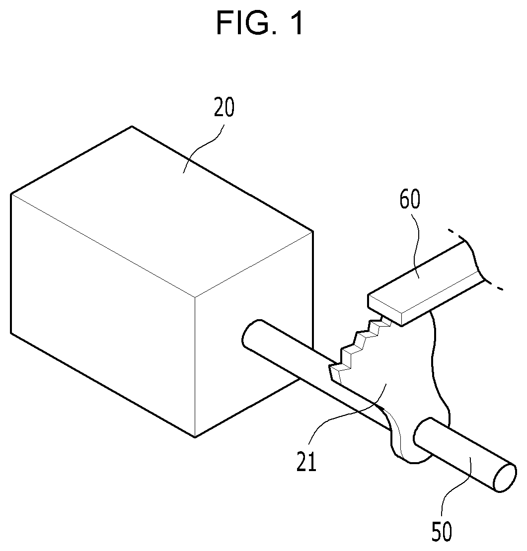
[0045]The present invention relates to the position learning system for an electric shift-by-wire system that is capable of sensing changes in the load of a motor 20 according to operations of a four-stage detent plate 50 and a detent spring 60 to learn positions of shift stages of the...

second embodiment

[0061]Next, an explanation on a position learning system for an electric shift-by-wire system according to the present invention will be in detail given with reference to FIGS. 3 and 6.

[0062]FIG. 6 is a front view showing a process of learning positions of shift stages of a two-stage detent plate in a position learning system for an electric shift-by-wire system according to a second embodiment of the present invention.

[0063]According to the second embodiment of the present invention, a position learning system for an electric shift-by-wire, which senses changes in the load of a motor 20 according to operations of a two-stage detent plate 50 and a detent spring 60 and thus learns positions of shift stages, includes a sensor 100 for sensing the current generated from the motor and a controller 200 for receiving current data until a shift stage P is switched to a shift stage (hereinafter, referred to as Not P) which is not the shift stage P or the shift stage (Not P) is switched to th...

third embodiment

[0070]Lastly, an explanation on a position learning system for an electric shift-by-wire system according to the present invention will be in detail given with reference to FIGS. 3 and 7.

[0071]FIG. 7 is a flowchart showing a process of learning positions of shift stages in a position learning system for an electric shift-by-wire system according to a third embodiment of the present invention.

[0072]According to the third embodiment of the present invention, a position learning system for an electric shift-by-wire, which senses changes in the load of a motor 20 according to operations of a four-stage detent plate 50 and a detent spring 60 and thus learns positions of shift stages, includes a sensor 100 for sensing the current generated from the motor and a controller 200 for receiving current data until a shift stage P is switched to a shift stage D and the shift stage D is switched back to the shift stage P from the sensor 100, learning positions of shift stages R and N through the c...


PUM


Abstract

The present invention relates to a position learning system for an electric shift-by-wire system, which senses changes in the load of a motor according to operations of a four-stage detent plate and a detent spring to learn positions of shift stages of the electric shift-by-wire system, the position learning system including: a sensor for sensing the current generated from the motor; and a controller for receiving current data until a shift stage P is switched to a shift stage D or the shift stage D is switched to the shift stage P from the sensor, learning positions of shift stages R and N through the received current data, and performing offset operations on the basis of the learned positions of the shift stages R and N to learn positions of the shift stages P and D.

Description

CROSS REFERENCE TO RELATED APPLICATION OF THE INVENTION[0001]The present application claims the benefit of Korean Patent Application No. 10-2018-0130066 filed in the Korean Intellectual Property Office on Oct. 29, 2018, the entire contents of which are incorporated herein by reference.BACKGROUND OF THE INVENTIONField of the Invention[0002]The present invention relates to a position learning system for an electric shift-by-wire system, and more particularly, to a position learning system for an electric shift-by-wire system that is capable of sensing variations in the amount of current generated from a motor according to changes in the load of the motor caused by an external force of a detent spring produced by a gap between a detent plate having hills and valleys formed on shift stages thereof and the detent spring, learning positions of the motor corresponding to the shift stages R and N, and performing offset operations at the learned positions of the shift stages R and N to recog...

Claims


Application Information

Patent Timeline
Patent Type & Authority Patents(United States)
IPC IPC(8): F16H63/38F16H63/34F16H61/28F16H59/08
CPCF16H63/3466F16H63/38F16H2059/086F16H2061/283F16H61/0204F16H61/32F16H63/30F16H61/28F16H2061/0087F16H59/044F16H61/24F16H2061/243F16H2061/326
Inventor CHO, HYOUNG SANG
Owner HYUNDAI KEFICO CORP
Learn More