Surgical guide wire assembly

a technology of guide wire and assembly, which is applied in the direction of guide wire, pipe supports, catheters, etc., can solve the problems of time-consuming and complicated production processes

Active Publication Date: 2021-04-20
HUANG HSIN PO
View PDF4 Cites 1 Cited by
  • Summary
  • Abstract
  • Description
  • Claims
  • Application Information

AI Technical Summary

Benefits of technology

[0005]An objective of the present invention is to provide a guide wire assembly capable of being produced in a time-saving fashion without compromising the capability against deformation to the guide wire.
[0013]Preferably, the coiled portions of the dispenser coil are partially and thermally joined to flat bottoms of the clips with line contact occurring between joined portions respectively located on the corresponding coiled portions of the dispenser coil and on the flat bottoms of the clips, and each joined portion takes a form of a segment traversing across the flat bottom of a corresponding clip or across one of the corresponding coiled portions of the dispenser coil. Because the dispenser coil is wound with the coiled portions thereof partially thermally joined to the multiple clips and being uniformly curved and flush with each other, the guide wire assembly can get rid of torsional and bending stresses as a result of twisted and bent coiled portion of the dispenser coil. The guide wire received inside the dispenser coil in turn won't easily incur deformation induced from the stresses. Also because the joined portions partially spread over the entire length of the dispenser coil, the guide wire assembly can be produced in a time-saving and efficient fashion without compromising the capability against deformation to the guide wire.

Problems solved by technology

As guide wire deformation may suggest complication such as vein or artery perforation, smooth movement of the guide wire inside a human body becomes a critical issue, such that care should be taken to keep guide wires in an undeformed condition to ensure smooth insertability thereof before being used in medical procedures.
However, the way of thermally bonding adjacent coiled portions over the entire length of the dispenser coil 31 may involve a more complicated and time-consuming production process.

Method used


Image

  • Surgical guide wire assembly
  • Surgical guide wire assembly
  • Surgical guide wire assembly

Examples


Embodiment Construction

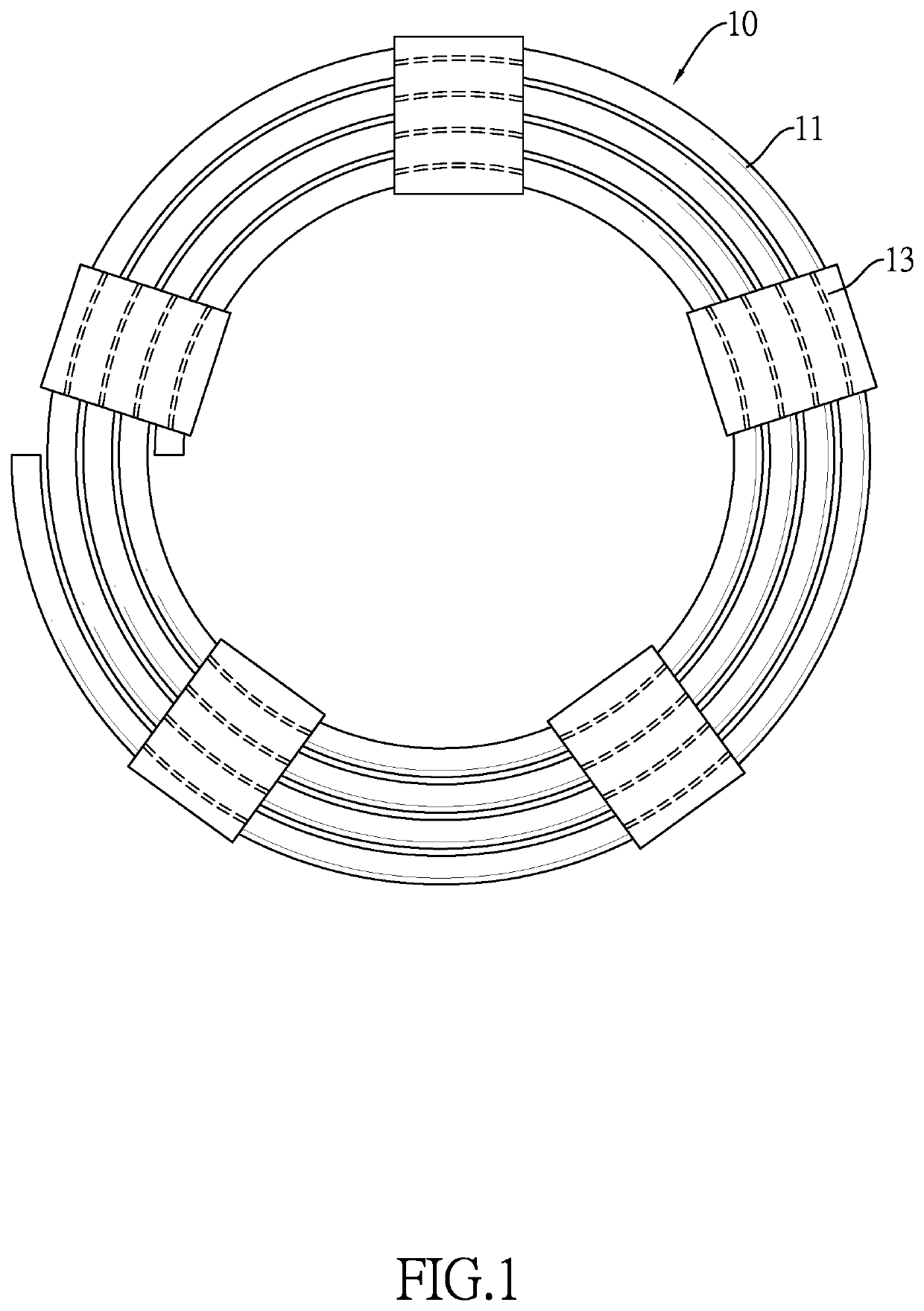
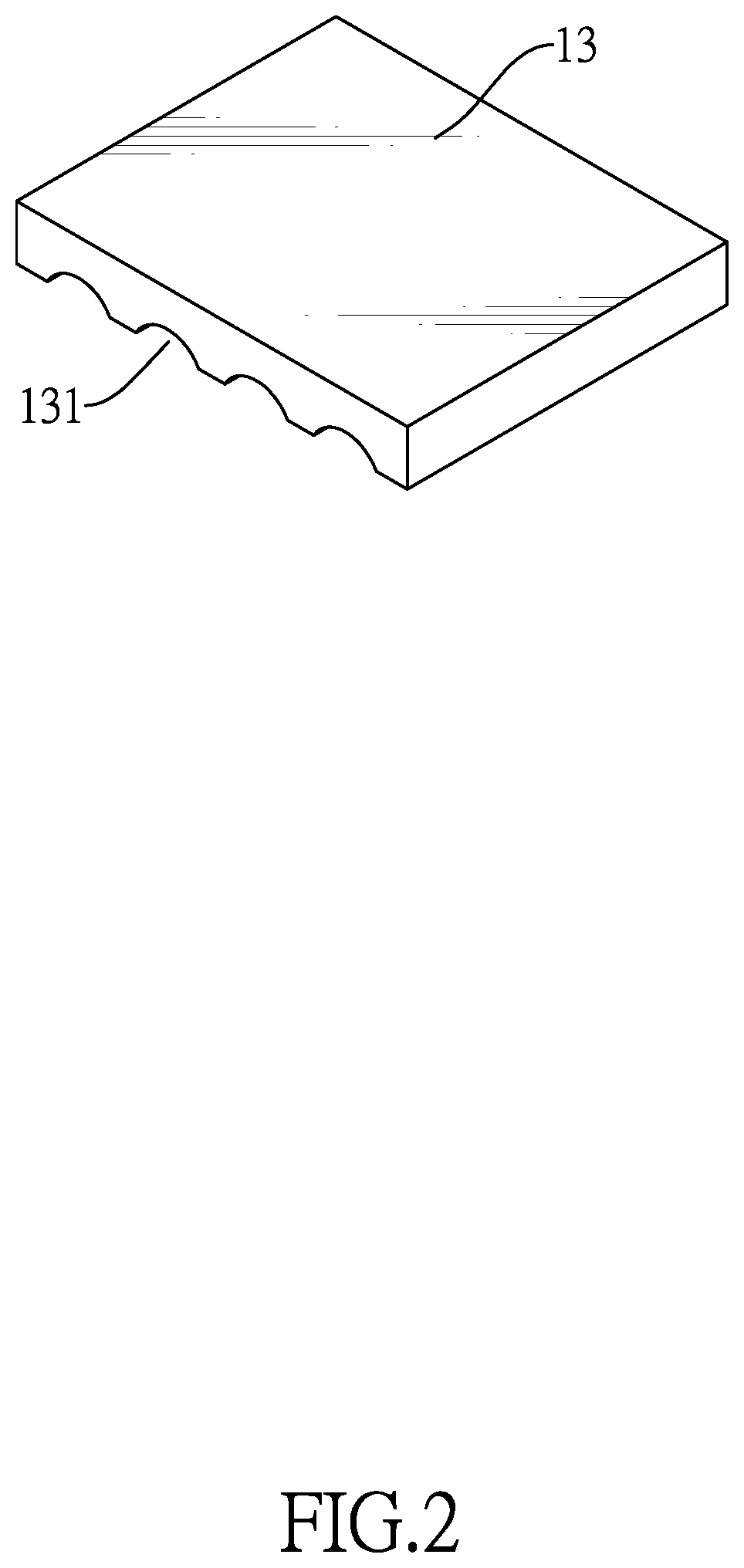
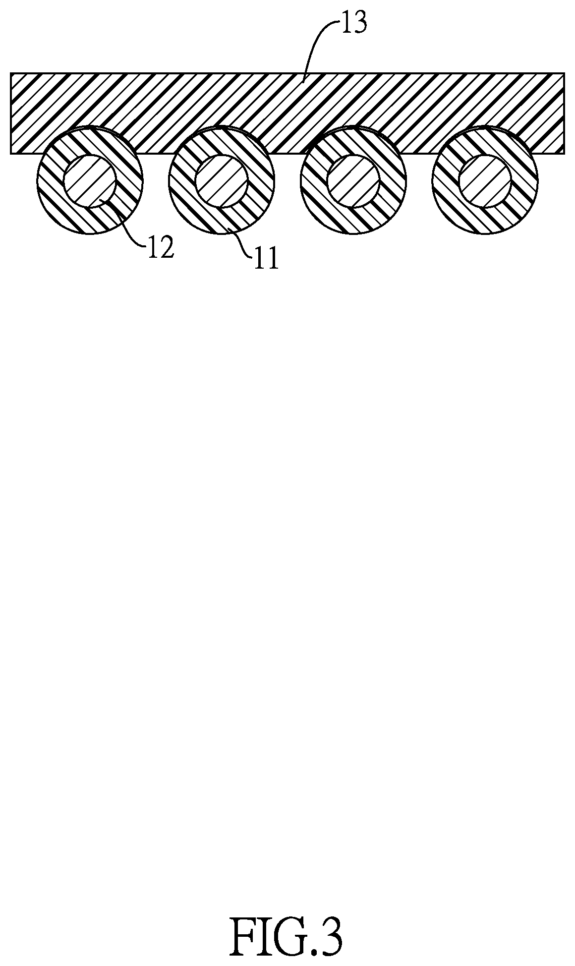
[0024]With reference to FIGS. 1 to 3, an embodiment of a guide wire assembly 10 in accordance with the present invention includes a dispenser coil 11, a guide wire 12 and multiple clips 13. The dispenser coil 11 is resilient, is made of a thermoplastic material, and is spirally coiled with coiled portions over an entire length of the dispenser coil 11. The guide wire 12 is resilient and metallic, and is received inside and protected by the dispenser coil 11. The multiple clips 13 are thermally joined to corresponding coiled portions of the dispenser coil 11 partially over the entire length of the dispenser coil 11, and are spaced apart from each other by gaps. Each clip 13 is resilient, is made of a thermoplastic material, and has multiple circular grooves 131 parallelly formed in and traversing across a bottom of the clip 13.

[0025]The entire coiled portions of the dispenser coil 11 are partially and thermally joined to inner walls of the multiple circular grooves 131 with line cont...


PUM


Abstract

A guide wire assembly includes a dispenser coil, a guide wire and multiple clips. The dispenser coil is resilient and spirally coiled with coiled portions over an entire length of the dispenser coil. The guide wire is resilient and received inside the dispenser coil. The multiple clips are thermally joined to corresponding coiled portions of the dispenser partially over the entire length of the dispenser coil, and are spaced apart from each other by gaps. Each clip is resilient and has multiple circular grooves parallelly formed in and traversing across a bottom of the clip. The dispenser coil is partially thermally joined to the multiple clips and the coiled portions of the dispenser coil are uniformly curved and flush with each other, ensuring that the guide wire assembly can be produced in a time-saving fashion without compromising the capability against deformation to the guide wire.

Description

BACKGROUND OF THE INVENTION1. Field of the Invention[0001]The present invention relates to a guide wire assembly and, more particularly, to a surgical guide wire assembly with a dispenser tube wound in a coiled form and partially thermally joined to and respectively retained in multiple clips.2. Description of the Related Art[0002]Surgical guide wires are used in minimally invasive medical applications to position devices such as catheters and stents. As guide wire deformation may suggest complication such as vein or artery perforation, smooth movement of the guide wire inside a human body becomes a critical issue, such that care should be taken to keep guide wires in an undeformed condition to ensure smooth insertability thereof before being used in medical procedures. To address such an issue, how to adequately package guide wires for shipping and storage appears to be one of the most important things to think about since guide wires are long and thin metallic wires.[0003]With ref...

Claims


Application Information

Patent Timeline
Patent Type & Authority Patents(United States)
IPC IPC(8): A61M25/00F16L3/223A61M25/09
CPCA61M25/002A61M25/09F16L3/223A61M25/09041
Inventor HUANG, HSIN-PO
Owner HUANG HSIN PO
Why Eureka
Try Eureka