Pressure-compensated load transfer device

a load transfer device and pressure compensation technology, applied in the direction of positive displacement liquid engines, machines/engines, gearing, etc., can solve the problems of over-capacity of shakers or actuators generating motion, no motion may be provided, etc., and achieve the effect of efficient load transfer

Active Publication Date: 2021-04-20
KEPCO NUCLEAR FUEL CO LTD
View PDF12 Cites 0 Cited by
  • Summary
  • Abstract
  • Description
  • Claims
  • Application Information

AI Technical Summary

Benefits of technology

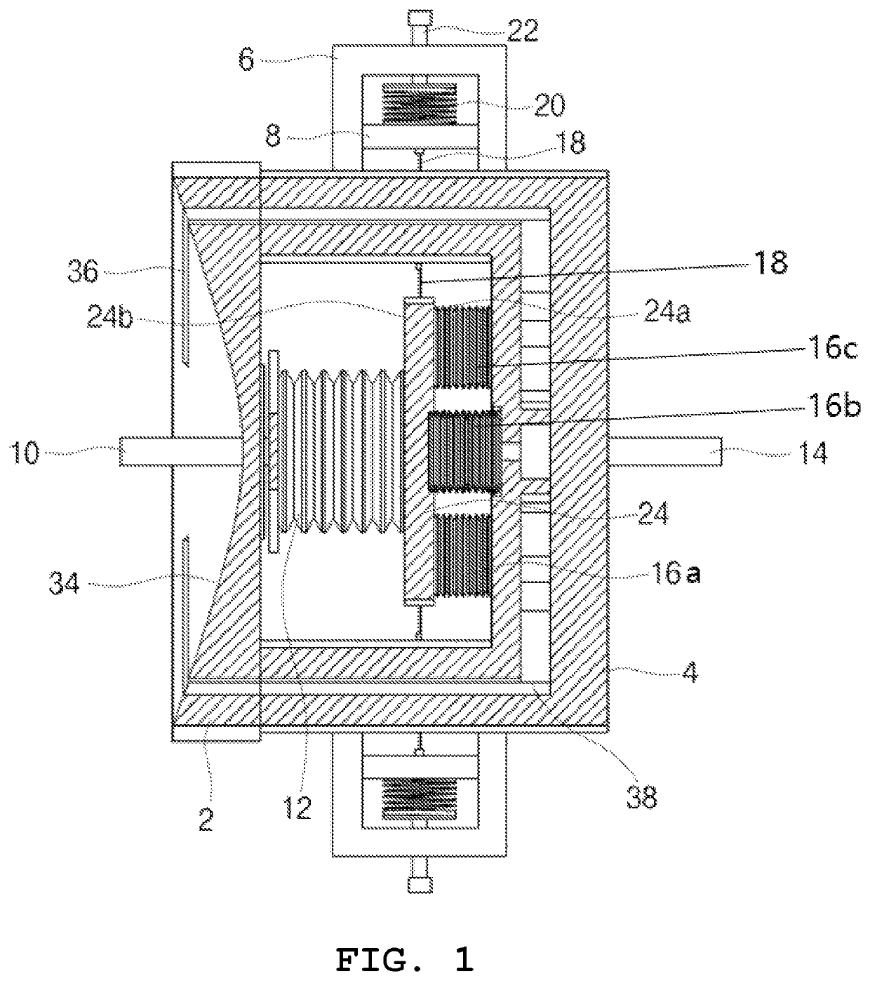
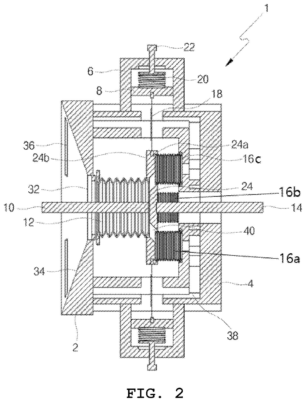
[0006]Accordingly, the present invention has been made keeping in mind the above problems occurring in the prior art, and an object of the present invention is to provide a pressure-compensated load transfer device able to uniformly provide load to a high-pressure side and a low-pressure side and lower stiffness in a moving direction, thereby minimizing loss in a load transferred.
[0011]According to the present invention, force balance is provided using static load acting on the bellows, and load can be more efficiently transferred using negative stiffness of the flexible beams.

Problems solved by technology

However, when the pressure of the high-pressure side is excessively higher than the pressure of the low-pressure side, the capacity of a shaker or an actuator generating motion may be exceeded and no motion may be provided.

Method used


Image

  • Pressure-compensated load transfer device
  • Pressure-compensated load transfer device
  • Pressure-compensated load transfer device

Examples


Embodiment Construction

[0020]Specific structural and functional descriptions of embodiments of the present invention disclosed herein are only for illustrative purposes of the embodiments of the present invention. The present invention may be embodied in many different forms without departing from the spirit and significant characteristics of the present invention. Therefore, the embodiments of the present invention are disclosed only for illustrative purposes and should not be construed as limiting the present invention. On the contrary, the present invention is intended to cover not only the exemplary embodiments, but also various alternatives, modifications, equivalents and other embodiments that may be included within the spirit and scope of the present invention as defined by the appended claims.

[0021]It will be understood that, although the terms “first”, “second”, etc. may be used herein to describe various elements, these elements should not be limited by these terms. These terms are only used to ...


PUM


Abstract

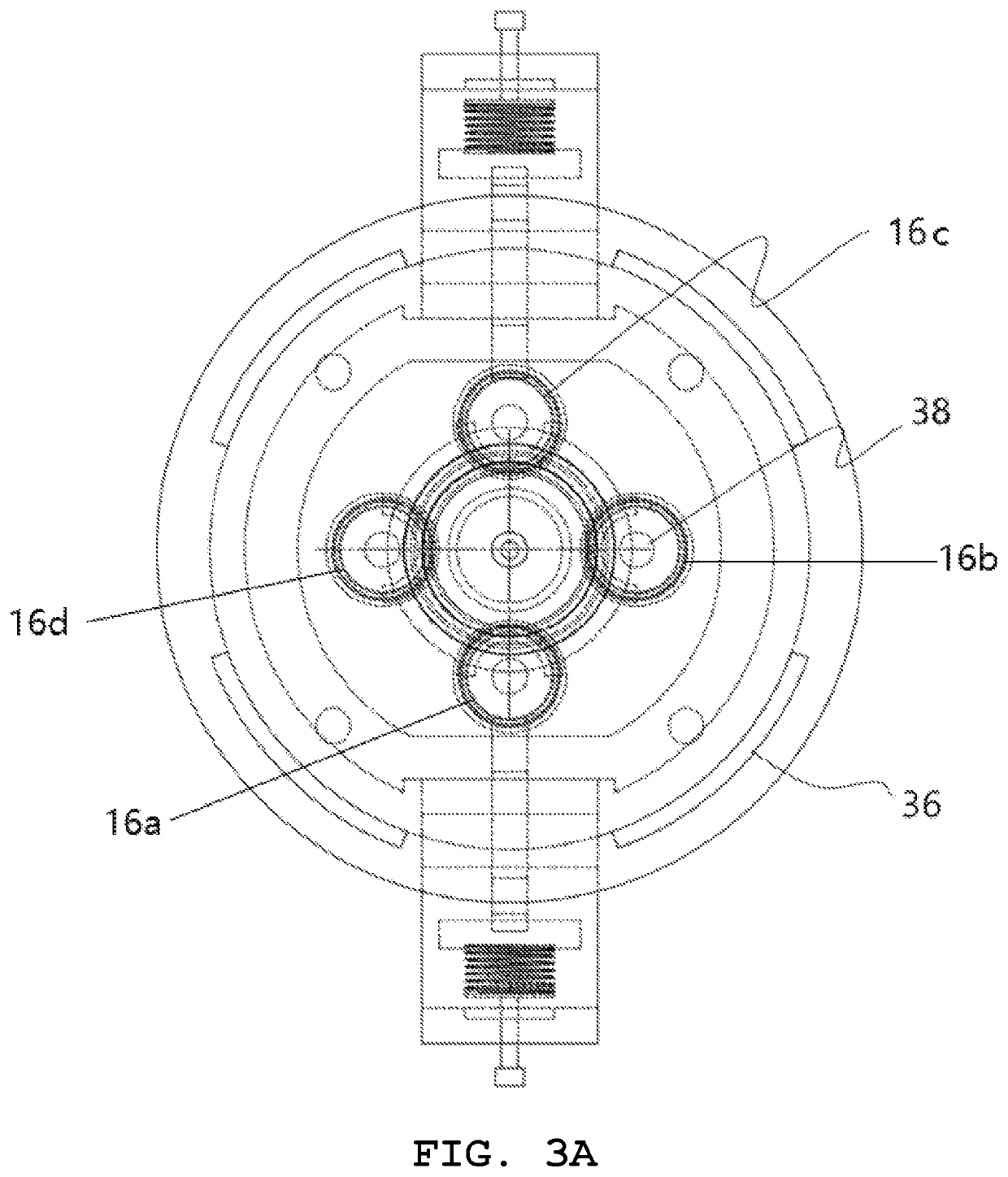
Provided are embodiments of a pressure-compensated load transfer device that includes a plate having a first shaft vertically installed on one side and a second shaft vertically installed on the other side to be coaxial with the first shaft. Also included is a first bellows having an opening in one side to surround the first shaft, with the other side thereof being fixed to the one side of the plate. Further included is a plurality of second bellows each having an opening in one end, with the other end thereof being attached to the other side of the plate. A housing is also included, and the housing includes a high-pressure working hole communicating with the opening of the first bellows and a high-pressure channel coplanar with the high-pressure working hole and communicating with the openings of the second bellows. The plate is back-and-forth movably received in the housing.

Description

CROSS-REFERENCE TO RELATED PATENT APPLICATIONS[0001]This patent application is a continuation of PCT / KR2016 / 007906, filed Jul. 20, 2016, which claims priority to Korean Patent Application No. 10-2016-0088443, filed Jul. 13, 2016, the entire teachings and disclosure of which are incorporated herein by reference thereto.TECHNICAL FIELD[0002]The present invention relates to a pressure-compensated load transfer device and, more particularly, to a pressure-compensated load transfer device using a flexible beam designed to have a high load transfer ratio.BACKGROUND ART[0003]To transfer motion between spaces having different levels of pressure, motion from a low-pressure side to a high-pressure side may be provided by applying a force equal to or greater than a force able to overcome the difference between the different levels of pressure. However, when the pressure of the high-pressure side is excessively higher than the pressure of the low-pressure side, the capacity of a shaker or an ac...

Claims


Application Information

Patent Timeline
Patent Type & Authority Patents(United States)
IPC IPC(8): F04B45/02F15B15/14F16H35/00F15B13/02F15B15/17
CPCF15B15/1404F15B13/02F15B15/1476F15B15/17F16H35/00F16J3/06F15B15/08F15B15/1423F15B2211/7051
Inventor KIM, KYOUNG-HONGKIM, JIN-SEONYOO, JONG-SUNGJEON, KYEONG-LAKEOM, KYONG-BOPARK, JOON-KYOOYOO, YOUNG-IKKWON, OH-JOONKIM, JOONG-JINLEE, TAE-KWON
Owner KEPCO NUCLEAR FUEL CO LTD
Why Eureka
Try Eureka