Method of determining a maximum acceptable alternating stress for a part that is subjected to cyclic loading; a unit for determining such a stress

a technology of cyclic loading and alternating stress, which is applied in the direction of material analysis, design optimization/simulation, instruments, etc., can solve the problems of reducing the application range of the above method, so as to achieve the effect of short computation time and particularly simple loading applied to the part during the digital simulation step (step a)

Active Publication Date: 2021-04-20
SN DETUDE & DE CONSTR DE MOTEURS DAVIATION S N E C M A
View PDF17 Cites 0 Cited by
  • Summary
  • Abstract
  • Description
  • Claims
  • Application Information

AI Technical Summary

Benefits of technology

[0047]Thus, in a preferred implementation, in step a), it is simulated digitally that, prior to the level period, the part is subjected to loading rising from a zero value up to the threshold value, during a loading rise period. The simulation taking account of this loading rise period makes it possible to represent in more realistic manner the rise in the stresses within the part under the effect of the applied loading.
[0071]Advantageously, in the method of the invention, the loading applied to the part during the digital simulation step (step a) is particularly simple, since it is constant during the level period. In particular, it much simpler than the cyclic stresses that are, in fact, applied to the material.
[0072]Advantageous, the method of the invention can be performed with particularly short computation time, unlike other simulation methods in which it is necessary to simulate applying alternating loading to the part.
[0074]Consequently, the method avoids the problems that are encountered in prior methods.

Problems solved by technology

Unfortunately, in particularly when developing parts that are subjected to high temperatures, and in particular that are subjected to loading at relatively high frequency (more than 1000 hertz (Hz)), e.g. the high pressure turbine blades of an aviation turbine engine, it is found that the above method does not give satisfactory results.
It can thus be understood that those conditions are too restrictive and often do not represent the frequencies of the loading that is actually applied to parts, which frequencies can be much higher.
However, it has been found that in practice that numerous parts withstand such stresses.
Consequently, a Goodman diagram of the kind described above, and the method of verifying the suitability of a part for being subjected to certain kinds of loading, as defined above in steps a) to c), cannot always be used for realistically evaluating whether a part, as defined in particular by its shape and its material, is suitable for being subjected to a certain predetermined number of loading cycles without breaking.

Method used


Image

  • Method of determining a maximum acceptable alternating stress for a part that is subjected to cyclic loading; a unit for determining such a stress
  • Method of determining a maximum acceptable alternating stress for a part that is subjected to cyclic loading; a unit for determining such a stress
  • Method of determining a maximum acceptable alternating stress for a part that is subjected to cyclic loading; a unit for determining such a stress

Examples


Embodiment Construction

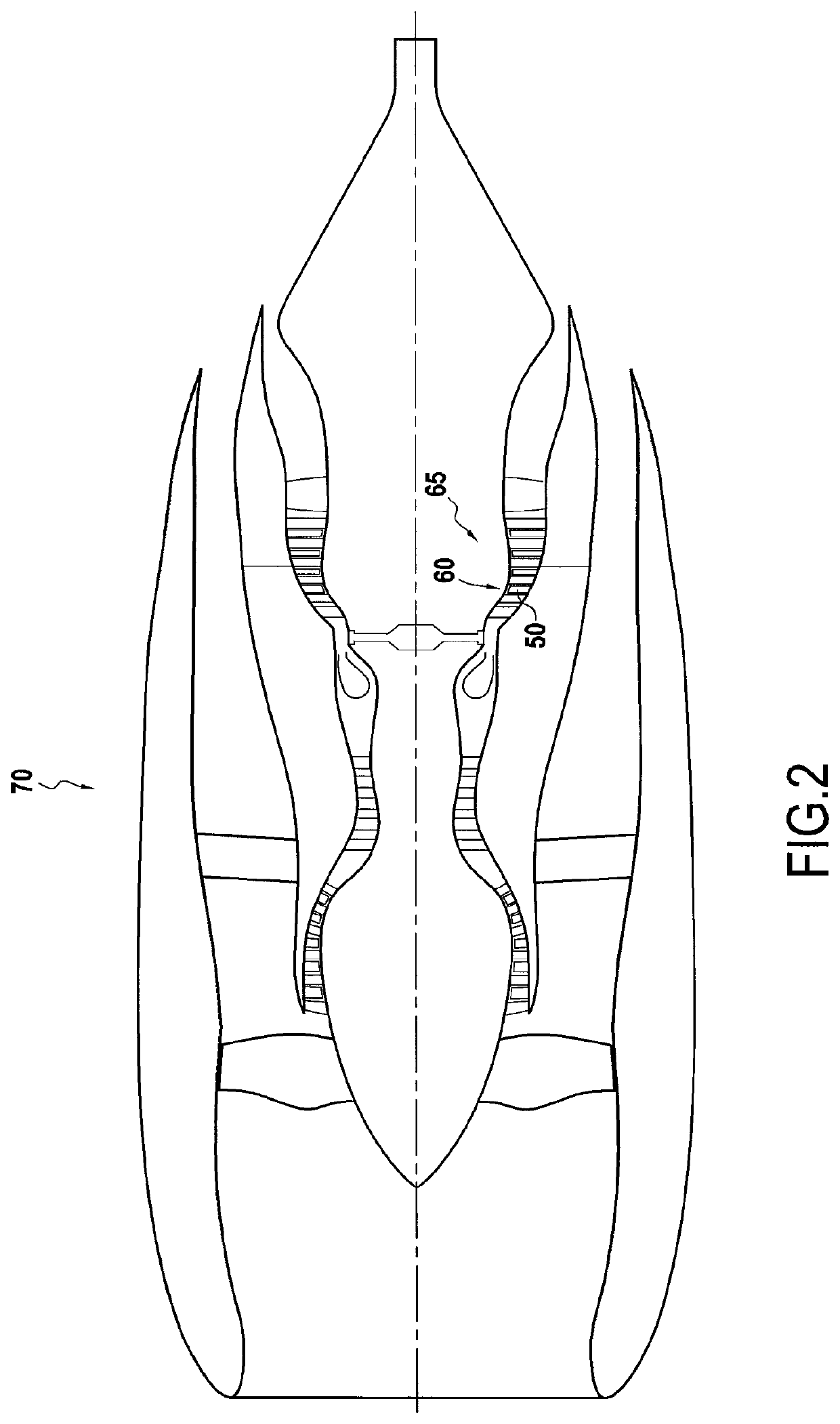
[0121]The invention is described below in the context of designing a blade 50 of a rotor wheel 60 of a high pressure turbine 65 in a turbine engine 70, as shown in FIG. 2.

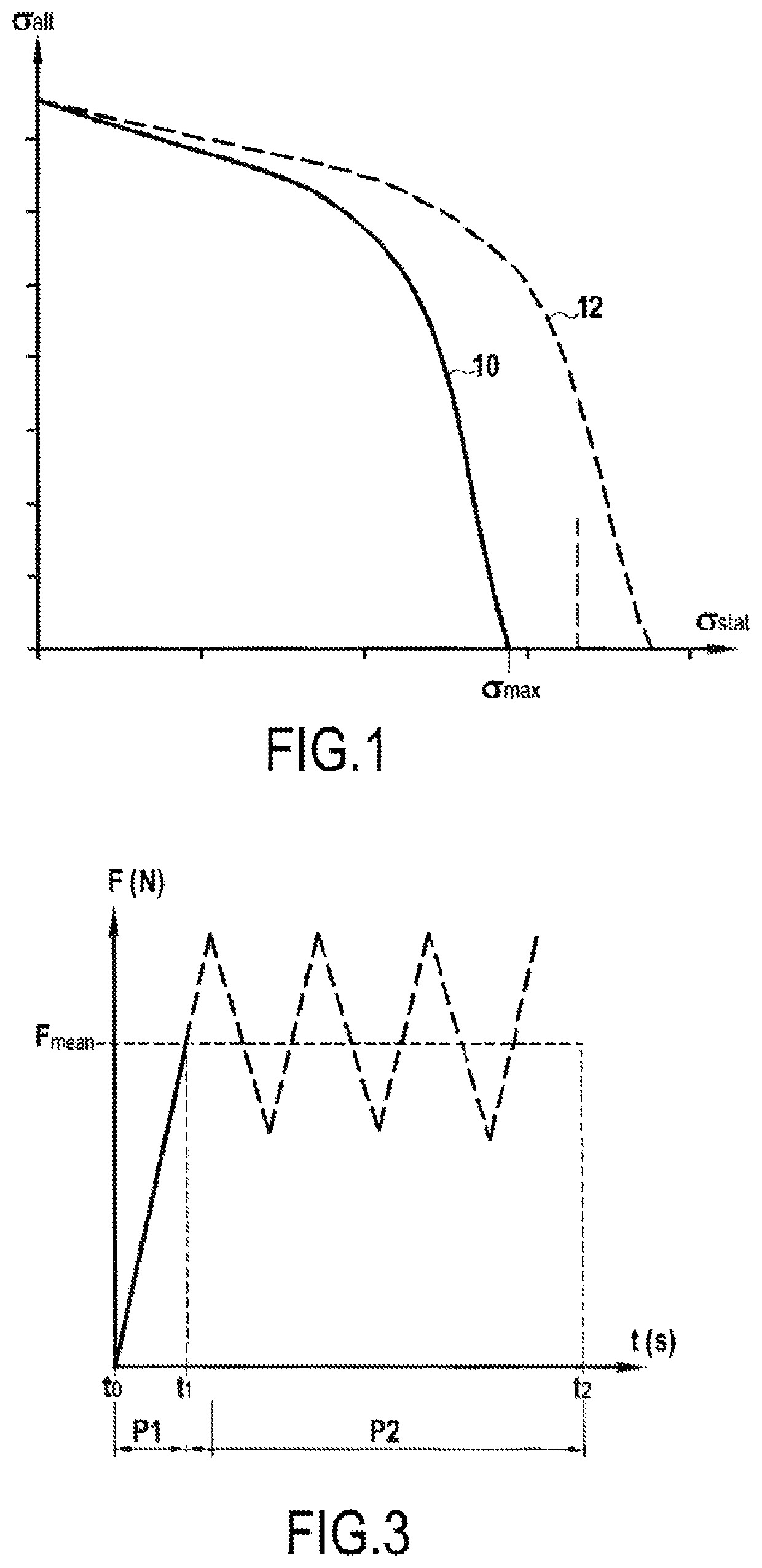
[0122]The loading to which the blade 50 is exposed while it is in use (i.e. throughout the entire lifetime of the engine 70) is shown in FIG. 3.

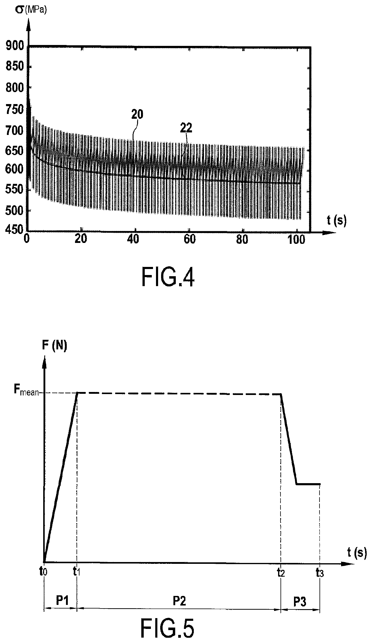
[0123]This figure shows the variations in the mechanical loading F to which the blade is subjected as a function of time t (in seconds). This loading corresponds to a force F (in newtons) acting mainly, but not only, in the longitudinal direction of the blade. The force F is due in particular to the centrifugal force to which the blade is subjected as a result of the rotor wheel rotating; it represents the stresses to which the part is subjected during a “mission” or stage of operation during which the part is in use, which may for example, for an aeroengine part, be a stage of an airplane taking off, etc.

[0124]As can be seen in FIG. 3, this loading, apart from a period P1 ...


PUM

PropertyMeasurementUnit
frequencyaaaaaaaaaa
frequencyaaaaaaaaaa
temperaturesaaaaaaaaaa

Abstract

A method of determining a maximum acceptable alternating stress at a point of a part subjected to cyclic loading: simulating that the part is subjected to constant loading equal to a threshold value during a level period, and assuming that the part has elasto-viscoplastic behavior; from the results of the simulation, determining a final static stress at the point at the end or after the end of the level period; and for the point under consideration, using a Goodman diagram to determine the maximum acceptable alternating stress, which is determined for a static stress equal to the final static stress; the duration of the level period being equal to the duration of the loading of the testpieces that were used to draw up the Goodman diagram.

Description

FIELD OF THE INVENTION[0001]The invention relates to means and methods serving to determine the maximum acceptable alternating stress at a point of a part that is to be subjected to substantially cyclic loading. Such loading may typically be centrifugal forces applied to rotating parts of rotary machines, or indeed loading applied to parts that are stationary, but arranged in the proximity of rotating parts.TECHNOLOGICAL BACKGROUND[0002]The invention lies in the context of certain modeling assumptions, as described below. These assumptions are themselves known in mechanics, for studying the dynamic behavior of parts.[0003]According to these assumptions, it is considered that the stress that is developed within a part being subjected to cyclic loading is the sum of two terms: a static stress term σstat that is the portion of the stress that varies slowly; and an alternating stress term σalt that is the portion of the stress that varies quickly; this last term contains in particular t...

Claims


Application Information

Patent Timeline
Patent Type & Authority Patents(United States)
IPC IPC(8): G06F30/15G06F30/20G01N3/32G06F111/10
CPCG06F30/20G01N3/32G06F30/15G01N2203/0214G06F2111/10
Inventor DESMEURE, GEOFFREY JUANCOMTE, FRANCOIS PIERRE MICHELGAUBERT, ANAIS SUZANNE AMELIELONGUET, ARNAUD CYRILCHEVALIER, MARINE LAETITIA CAMILLEHANSOM, MICHAEL PIERSLANCIAUX, LUCIE MARIE IDA
Owner SN DETUDE & DE CONSTR DE MOTEURS DAVIATION S N E C M A
Why Eureka
Try Eureka