
Telescopic single-legged portable working chair
a working chair and single-legged technology, applied in the field of single-legged portable working chairs, can solve the problems of inability to help reduce the load applied to the lower body, knees, ankles, hip joints, etc., and achieve the effect of reducing the power consumption, reducing the injury to the user's body, and reducing the load applied to the user's joints and muscles
- Summary
- Abstract
- Description
- Claims
- Application Information
AI Technical Summary
Benefits of technology
Problems solved by technology
Method used
Image

Examples
Embodiment Construction
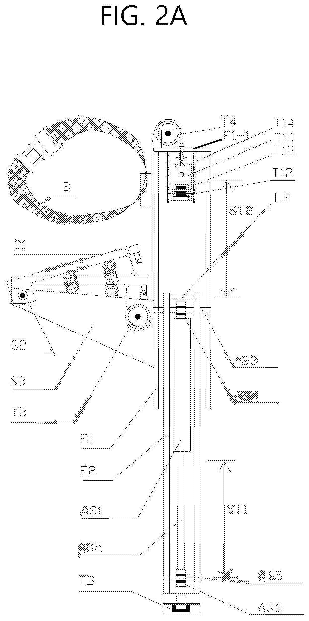
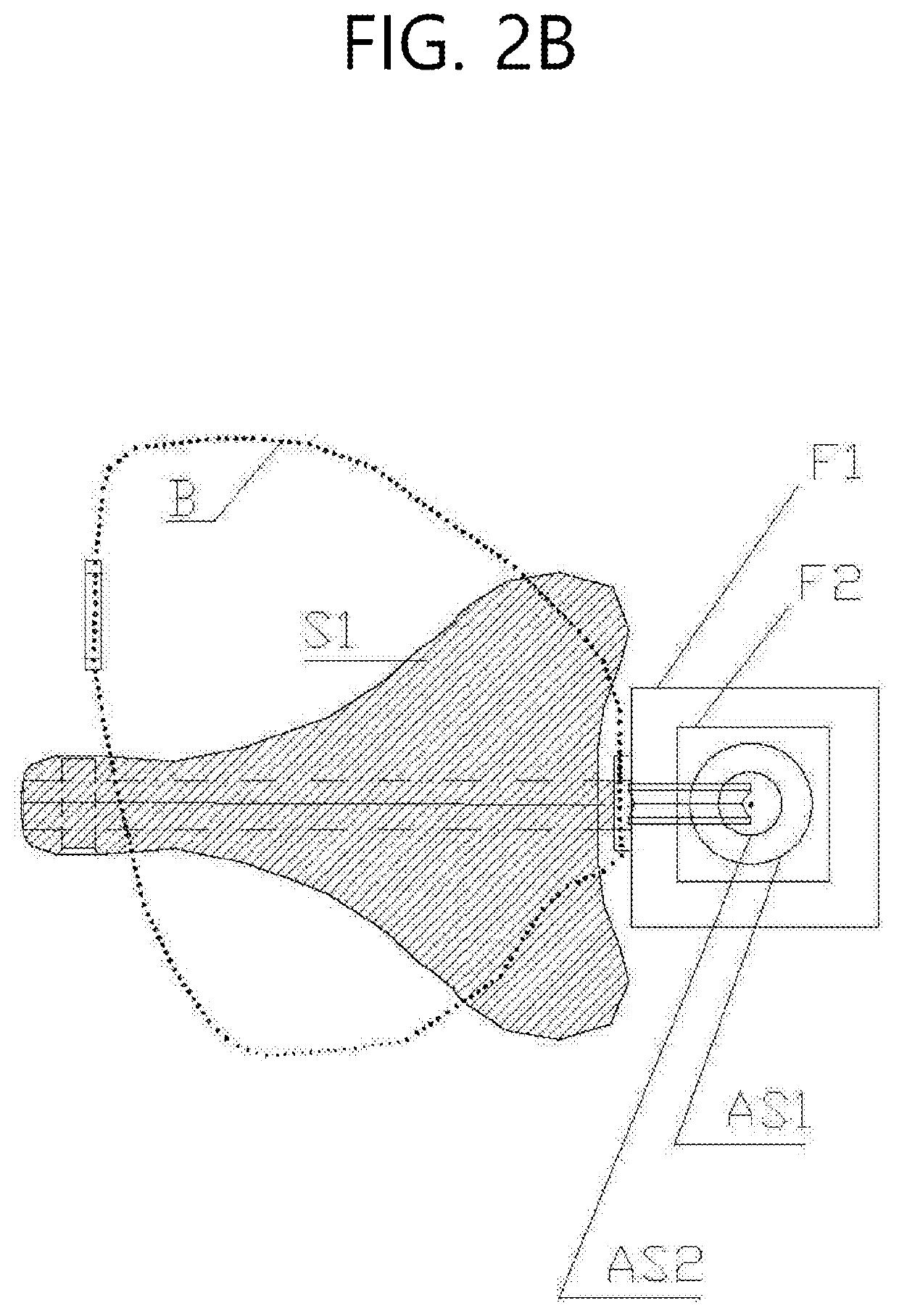
[0016]In FIG. 2A and FIG. 2B,
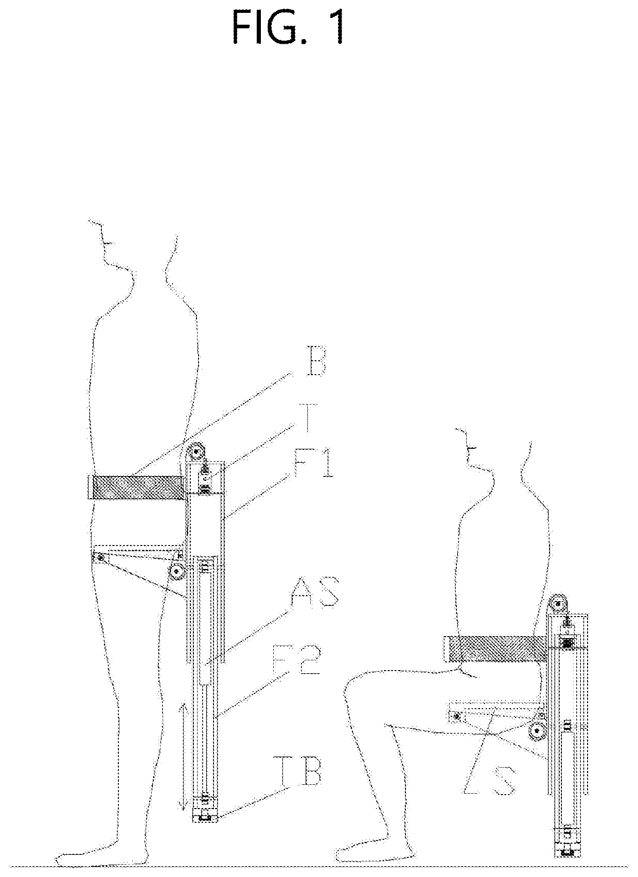
[0017]The entire structure and elements of the single-legged portable working chair are illustrated. The spring body AS is disposed inside the lower frame F2, a spring upper eye rod AS4 is connected to the upper frame F1 through an upper eye rod shaft AS3, a spring lower eye rod AS6 is dynamically connected to the lower frame F2 through a lower eye rod shaft AS5, wherein, upon operation of the spring body, the lower frame F2 moves inside the upper frame F1 in the same direction as that of the spring body by the same distance as that of the spring body. That is, a stroke ST1 of the spring body and a lower frame stroke ST2 are the same. Within a trigger frame T14 installed under a top cover F1-1 of the upper frame F1, there are provided a trigger arm roller T13, a trigger arm T10, and a trigger slider T8. The trigger arm T10 restricts or releases a lower frame locking bar LB going upward through the trigger arm roller T13 to control operation of the spring...
PUM
 Abstract
Description
Claims
Application Information