Air conditioning device for vehicle

a technology for air conditioning devices and vehicles, which is applied to vehicle heating/cooling devices, vehicle components, transportation and packaging, etc., can solve the problems of inability to perform dehumidification of air and inability to achieve continuous dehumidification of air, and achieve the effect of suppressing sensible heat transfer

Active Publication Date: 2021-04-27
HIGHLY MARELLI JAPAN CORPORATION
View PDF13 Cites 0 Cited by
  • Summary
  • Abstract
  • Description
  • Claims
  • Application Information

AI Technical Summary

Benefits of technology

[0006]Here, it is conceivable to do the following in order to make continuous dehumidification of air possible.
[0013]In light of that, there is demand for making it possible to suppress sensible heat transfer via the desiccant material between the air subject to dehumidification and the air for recovery.
[0015]With this aspect, it is possible to suppress sensible heat transfer via the desiccant part between the air subject to dehumidification and the air for recovery.

Problems solved by technology

However, with the air conditioning device of the above mentioned publication, when regenerating the moisture absorbing agent, it is not possible to perform dehumidification of the air, and thus, continuous dehumidification of air is not possible.

Method used


Image

  • Air conditioning device for vehicle
  • Air conditioning device for vehicle
  • Air conditioning device for vehicle

Examples


first embodiment

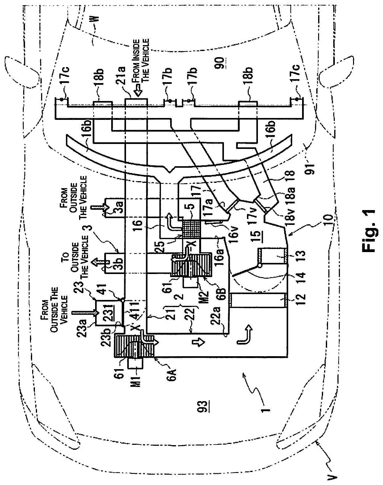
[0028]Following, a first embodiment of the present invention is explained using an example of a case when the air subject to dehumidification is air for which the temperature is regulated (conditioned air) using a temperature regulating unit 10 of an air condition device 1.

[0029]FIG. 1 is a schematic block diagram of the air condition device for a vehicle 1 of the present embodiment.

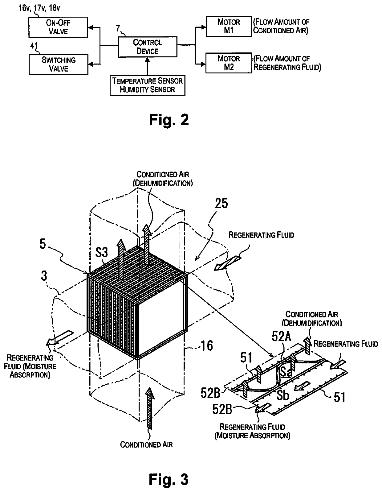
[0030]FIG. 2 is a drawing for explaining the control object of a control device 7 provided in the air condition device for a vehicle 1. The control device 7 includes a computer that executes a predetermined control program and a memory that stores information used for various control programs and various control processes. The computer includes, for example, a central processing unit (CPU) or a micro-processing unit (MPU).

[0031]As shown in FIG. 1, the air conditioning device for a vehicle 1 has the temperature regulating unit 10 for regulating conditioned air (air for which the temperature has been regul...

second embodiment

[0229]Next, an air conditioning device 1A of a second embodiment of the present invention is explained.

[0230]FIG. 6 is a schematic block diagram of the air conditioning device for a vehicle 1A of the present embodiment.

[0231]As shown in FIG. 6, the air conditioning device 1A has a contact area 26 provided with the defroster duct 16 and the second flow path 3 in contact with each other's wall parts.

[0232]With this contact area 26, a desiccant part 5A is provided straddling the defroster duct 16 and the second flow path 3.

[0233]The desiccant part 5A is provided in a direction (orthogonal direction) intersecting with the flow through direction of the air in the defroster duct 16 and the second flow path 3.

[0234]FIGS. 7A and 7B are drawings for explaining the desiccant part 5A. FIG. 7A is a drawing for explaining the basic configuration and operation of the desiccant part 5A, and FIG. 7B is a perspective view for explaining the placement of the desiccant part 5A.

[0235]As shown in FIG. 7...

third embodiment

[0267]Next, an air conditioning device 1B of a third embodiment of the present invention is explained.

[0268]FIG. 8 is a schematic block diagram of the air conditioning device for a vehicle 1B of the present embodiment.

[0269]As shown in FIG. 8, the air conditioning device 1B has an intersection area 27 in which the second flow path 3 intersects with the flow passage 21 of the first flow path 2, and the desiccant part 5 is provided in this intersection area 27.

[0270]During the heating operation in winter, when the operating mode of the air conditioning device 1B is the desiccant mode, the air with a high temperature and absolute humidity incorporated from inside the vehicle interior 90 (internal air: air subject to dehumidification) flows through the intersection area 27. This internal air is air of a higher temperature than the regenerating fluid (external air: air for recovery) that flows through the second flow path 3. For that reason, the same as with the case of the first embodim...


PUM


Abstract

An air conditioning device for a vehicle includes a first flow path through which air subject to dehumidification flows, a second flow path through which air for recovery flows, a desiccant part and a controller. The desiccant part is fluidly communicated with the first and second flow paths, and configured to adsorb moisture contained in the air subject to dehumidification, and to discharge the moisture to the air for recovery. The controller is configured to control an air volume of the air subject to dehumidification and an air volume of the air for recovery so that the air volume of the air for recovery is less than the air volume of the air subject to dehumidification, after the air volume of the air for recovery reaches a prescribed air volume for achieving a target dehumidification amount of the air subject to dehumidification.

Description

CROSS-REFERENCE TO RELATED APPLICATIONS[0001]This application claims priority to Japanese Patent Application No. 2017-176201, filed on Sep. 13, 2017. The entire disclosure of Japanese Patent Application No. 2017-176201 is hereby incorporated herein by reference.BACKGROUNDField of the Invention[0002]The present invention relates to an air conditioning device for a vehicle.Background Information[0003]Disclosed in Japanese Laid-Open Patent Publication No. H08-067136 is an air conditioning device for a vehicle for which a moisture absorption device is placed on a flow path for air for air conditioning.[0004]The moisture absorption device of this air conditioning device is configured by combining a moisture absorbing agent (desiccant material) and a regenerating heater. With this moisture absorption device, the moisture contained in the air that flows through the inside of the flow path is adsorbed by the moisture absorbing agent, which dehumidifies the air. Furthermore, when the moistur...

Claims


Application Information

Patent Timeline
Patent Type & Authority Patents(United States)
IPC IPC(8): B60H3/02B60H1/00
CPCB60H3/024B60H1/00985B60H2001/00214B60H2003/028
Inventor NAKAMURA, TAKASHIMARUYAMA, TOMOHIROKAWAI, SHUSUKE
Owner HIGHLY MARELLI JAPAN CORPORATION
Why Eureka
Try Eureka