An outdoor moisture-proof and energy-saving distribution box

A technology for power distribution boxes and boxes, which is applied in substation/power distribution device shells, electrical components, substation/switch layout details, etc., which can solve problems such as humid gas cannot be discharged in time, hidden safety hazards, etc., and achieve good use effects and improved Fluidity and long service life

Active Publication Date: 2022-05-17
天润双翎(北京)科技有限公司
View PDF11 Cites 0 Cited by
  • Summary
  • Abstract
  • Description
  • Claims
  • Application Information

AI Technical Summary

Problems solved by technology

[0004] The purpose of the present invention is to solve the disadvantages in the prior art that the humid gas in the existing outdoor distribution box cannot be discharged in time, thus having certain potential safety hazards, and proposes an outdoor moisture-proof and energy-saving distribution box

Method used


Image

  • An outdoor moisture-proof and energy-saving distribution box
  • An outdoor moisture-proof and energy-saving distribution box
  • An outdoor moisture-proof and energy-saving distribution box

Examples


Embodiment 1

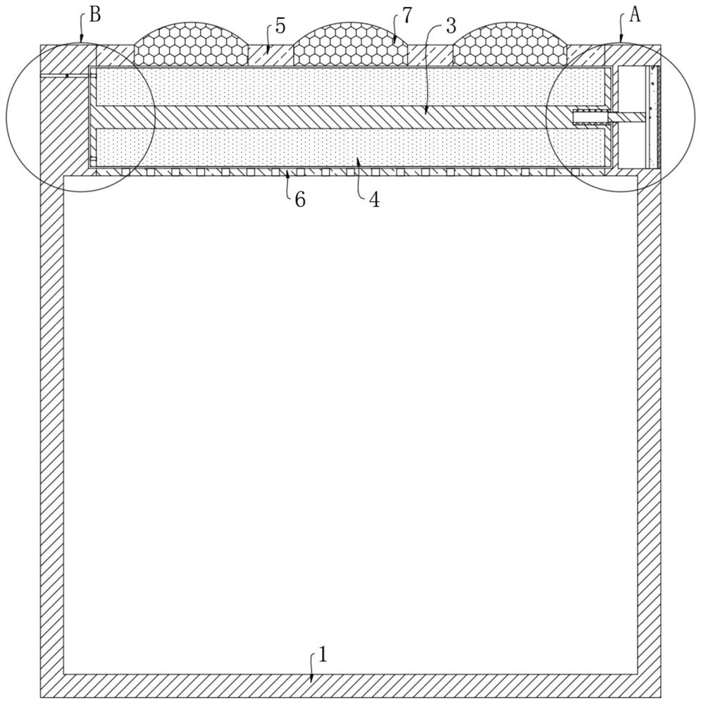
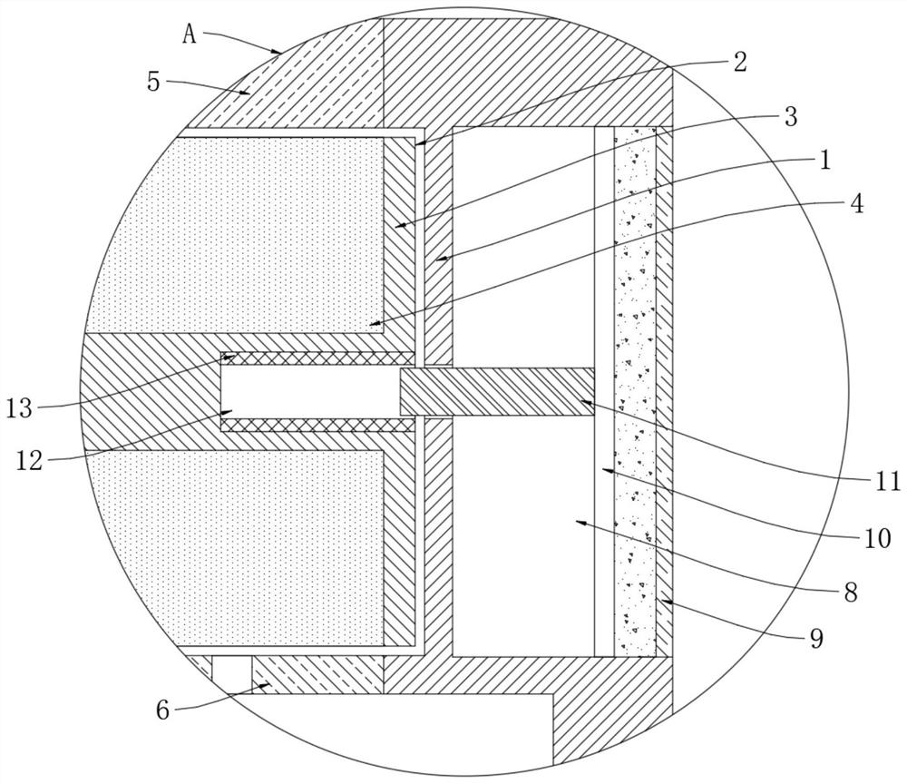
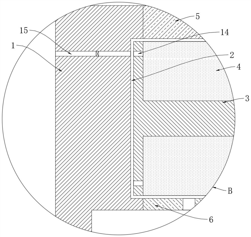
[0023] refer to Figure 1-4 , a moisture-proof and energy-saving distribution box for outdoor use, including a box body 1, a cylindrical groove 2 is opened on the upper end of the box body 1, and a turntable 3 is rotatably connected in the cylindrical groove 2, and the side wall of the turntable 3 is sealed and slidingly connected with the cylindrical groove 2 , the side wall of the turntable 3 is symmetrically provided with placement slots 4, and each placement slot 4 is filled with silica gel desiccant. The silica gel desiccant has good water absorption, and the silica gel desiccant can be dehydrated and regenerated in a high temperature environment after absorbing water. In order to restore the water absorption, and then reuse, the upper and lower walls of the cylindrical tank 2 and the upper end surface and inner top wall of the box body 1 are respectively provided with an upper channel and a lower channel corresponding to the placement tank 4, and an upper channel and a lo...

Embodiment 2

[0029] refer to Figure 5 The difference between this embodiment and Embodiment 1 is that the sealed space formed by the side of the piston plate 10 away from the driving area and the rectangular groove 8 is the driven area, and the space between the driven area and the inner top wall and upper end surface of the box body 1 One-way air intake pipe 16 and one-way exhaust pipe 17 are communicated with respectively, and the second one-way valve and the third one-way valve are respectively installed in one-way air intake pipe 16 and one-way exhaust pipe 17, and the second one-way valve Only the gas or liquid inside the box body 1 is allowed to enter the driven area through the one-way inlet pipe 16, and the third one-way valve only allows the gas or liquid inside the driven area to enter the outside world through the one-way exhaust pipe 17.

[0030] This embodiment can illustrate its functional principle through the following operation mode: when negative pressure is generated in...


PUM


Abstract

The invention discloses a moisture-proof and energy-saving distribution box for outdoor use, which comprises a box body. A cylindrical groove is arranged at the upper end of the box body. A turntable is rotatably connected in the cylindrical groove, and the side wall of the turntable is sealed and slidably connected with the cylindrical groove. The side wall of the turntable is symmetrically provided with placement grooves, and each of the placement grooves is filled with desiccant, and the upper and lower groove walls of the cylindrical groove, the upper end surface of the box body, and the inner top wall are respectively provided with placement grooves. Corresponding to the upper channel and the lower channel, the upper channel and the lower channel are respectively sealed and fixed with a light-transmitting plate and a gas-permeable plate. In the present invention, by using the evaporation and liquefaction of the driving agent as the driving force and cooperating with the transmission of the threaded rod and the threaded sleeve, the turntable can be driven to continuously rotate in one direction, so that the desiccant in the two storage tanks on the turntable can alternately absorb water Dehumidification, dehydration regeneration, can continuously dehumidify the inside of the box, and has a long service life, without frequent replacement of desiccant, the use effect is good.

Description

technical field [0001] The invention relates to the technical field of power distribution equipment, in particular to an outdoor moisture-proof and energy-saving power distribution box. Background technique [0002] As a protective device for power equipment in power transmission equipment, the distribution box is particularly important for its safety and protection. Many distribution boxes need to be installed outdoors during long-distance power transmission. However, in rainy seasons or humid environments, power distribution The inside of the box is often very humid. At the same time, in order to prevent sundries such as mosquitoes from entering the box, the interior of the conventional outdoor distribution box is generally closed, which makes the humid gas inside the box unable to be discharged in time. When the inside of the distribution box is wet When there is too much gas, it is easy to cause electric leakage, which has certain potential safety hazards. Although some ...

Claims


Application Information

Patent Timeline
Patent Type & Authority Patents(China)
IPC IPC(8): H02B1/28H02B1/56H02B1/46
CPCH02B1/28H02B1/56H02B1/46Y02A30/14
Inventor 郑佳
Owner 天润双翎(北京)科技有限公司
Why Eureka
Try Eureka