
Novel membrane drying machine

A drying machine, a new type of technology, applied in the separation of dispersed particles, chemical instruments and methods, separation methods, etc., can solve problems such as cost increase, dust generation, threat to the health of operators and other personnel, etc., to improve use efficiency, energy low consumption effect

Pending Publication Date: 2018-02-16
重庆华晨智创数控设备有限公司
View PDF9 Cites 0 Cited by
  • Summary
  • Abstract
  • Description
  • Claims
  • Application Information

AI Technical Summary

Problems solved by technology

[0003] In the prior art, the compressed air enters the drying tower for drying after passing through the secondary filtration (1 μm filter + 0.01 μm filter), and the interior of the drying tower is adsorbed by granular adsorption materials processed by many chemical dusts In the process of production and use, some particles will be broken and dust will be generated due to repeated pressure changes in the filling and drying container; Exhausted into the air, it seriously threatens the health of operators and other personnel; in fact, the cost of isolating this kind of dust is very high. In the actual cooling process, the compressed air must be directly blown at a relatively large pressure (0.1Mpa) and flow rate. In the processing area, adding a dust isolation net will only reduce the air pressure and flow rate at the outlet, and the dust isolation net also needs to be replaced frequently; the trouble and cost increase caused by this is also what the user does not want to see of

Method used


Image

  • Novel membrane drying machine
  • Novel membrane drying machine

Examples


Embodiment Construction

[0019] The preferred embodiments of the present invention will be described in detail below with reference to the accompanying drawings.

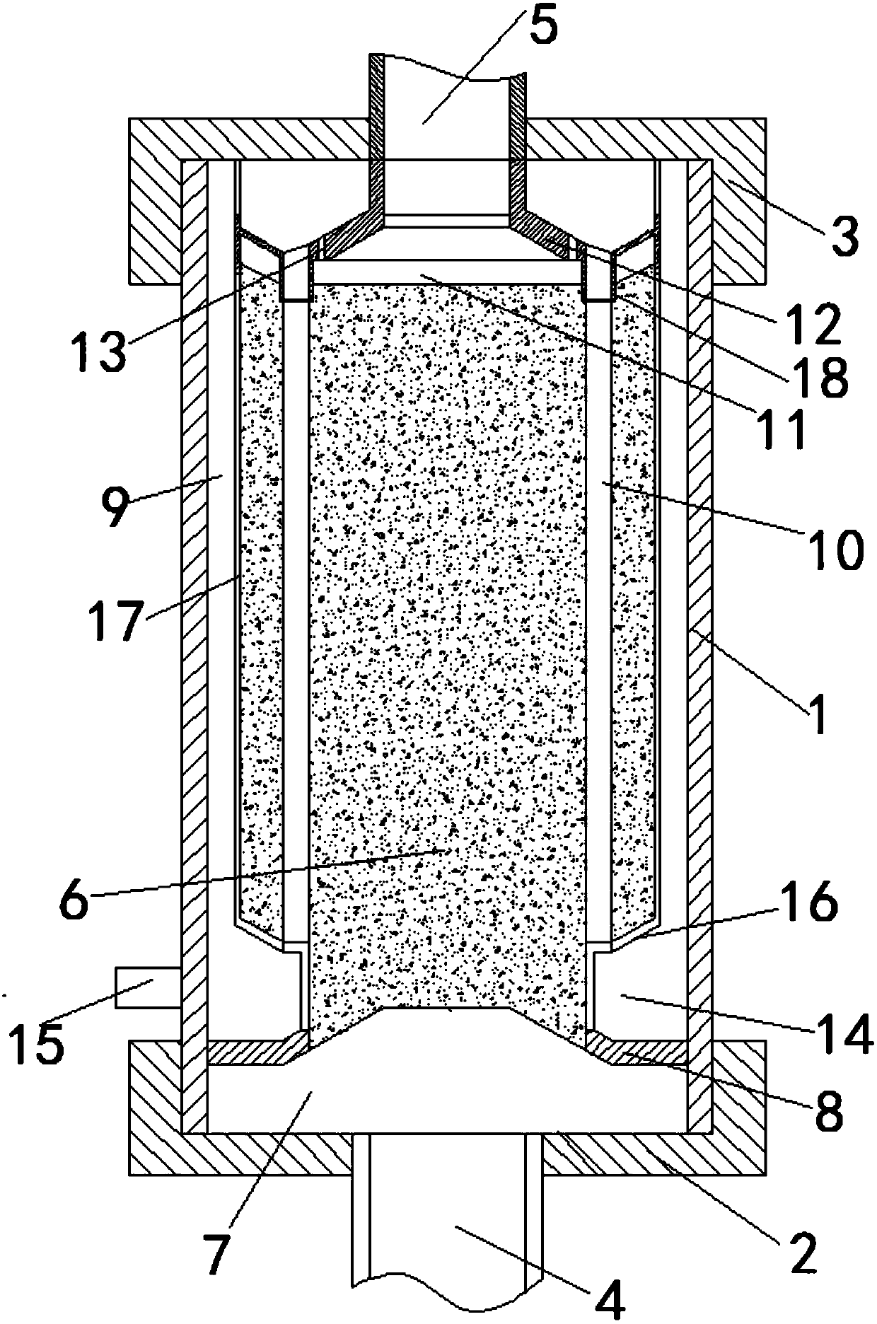
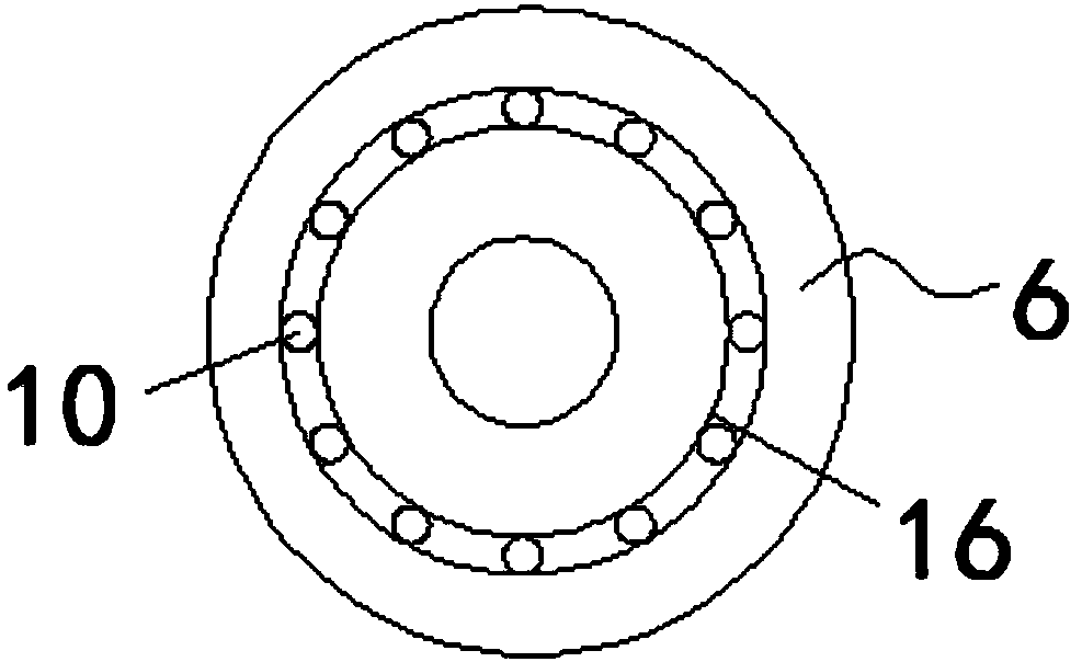
[0020] Such as figure 1 Shown is the structural representation of the novel membrane dryer of the present invention; figure 2 Shown is a schematic structural view of the hollow fiber membrane filter element in the novel membrane dryer of the present invention; a novel membrane dryer of the present invention includes a tank body 1 and a lower installation cover 2 and an upper installation cover installed on the bottom and top of the tank body 1 3. The tank body 1 is provided with a hollow fiber silk membrane filter element 6, the lower mounting cover 2 is provided with an air intake pipe 4 communicating with the tank body 1, and the upper mounting cover 3 is provided with a The air outlet pipe 5 connected inside, the water vapor exhaust pipe 15 is arranged on the side wall of the tank body 1, and the water vapor exhaust pipe 15 communicati...


PUM


Abstract

The invention discloses a novel membrane drying machine which comprises a tank body, a gas inlet pipe, a gas outlet pipe and a vapor discharge pipe, wherein a hollow fiber membrane filter element is arranged in the tank body; a vapor volatilization chamber is arranged between the hollow fiber membrane filter element and the inner wall of the tank body; a partition plate is arranged in the tank body; a mounting hole is formed in the partition plate; a gas inlet chamber is arranged under the partition plate; a dry gas discharge chamber is arranged on the hollow fiber membrane filter element; a gas guide valve is arranged in the dry gas discharge chamber; a gas outlet communicated with the dry gas discharge chamber is formed in the gas guide valve; the hollow fiber membrane filter element isradially and annularly provided with a dry gas channel; the upper end of the dry gas channel is communicated with the gas guide valve; the lower end of the dry gas channel is communicated with the vapor volatilization chamber. In the novel membrane drying machine, the gas guide valve is arranged, and the hollow fiber membrane filter element is radially and annularly provided with the dry gas channel, so that the filtering and drying efficiency of compressed air can be improved by utilizing the dry gas channel, and the dry gas channel is beneficial for drying of the hollow fiber membrane filterelement. Therefore, the service efficiency of the hollow fiber membrane filter element is improved.

Description

technical field [0001] The invention belongs to the technical field of cold air jet machine parts, and in particular relates to a novel membrane dryer. Background technique [0002] During the machining process of metal, a large amount of heat will be generated due to cutting between the tool and the workpiece. If it is not cooled, it will have many adverse effects on the machining accuracy and the physical and chemical properties of the workpiece; the existing cooling methods include coolant cooling and air cooling. Cooling; air cooling has the advantages of convenient use, storage, cleaning and handling, and will not cause adverse consequences to the environment and the health of the operator, and the cost of use and handling is low. Therefore, air cooling metal machining (dry processing) generally received attention. [0003] In the prior art, the compressed air enters the drying tower for drying after passing through the secondary filtration (1 μm filter + 0.01 μm filte...

Claims


Application Information

Patent Timeline
Patent Type & Authority Applications(China)
IPC IPC(8): B01D53/26B01D53/22
CPCB01D53/22B01D53/268B01D2053/224
Inventor 章海涛翁喻松税继光周昌华
Owner 重庆华晨智创数控设备有限公司
Learn More