Filter device and system and clogging monitoring method

a filter device and filter system technology, applied in the direction of filtration separation, separation processes, chemistry apparatuses and processes, etc., can solve the problems of clogging of the first filter zone more quickly than the second filter zone, and achieve the effect of convenient maintenance and more reliabl

Active Publication Date: 2021-05-04
SAFRAN FILTRATION SYST
View PDF8 Cites 0 Cited by
  • Summary
  • Abstract
  • Description
  • Claims
  • Application Information

AI Technical Summary

Benefits of technology

[0016]An object of the invention is therefore to make more reliable the detection of the clogging condition of a filter device, especially in order to facilitate the operations of maintenance of the device.
[0024]In such a filter device, the presence of the constriction in the second circuit has the effect of initially orienting the fluid stream mainly through the first circuit. This has the effect that the first filter zone becomes clogged more quickly than the second filter zone, even though these two filter zones have identical filtration efficiencies. Therefore, the pressure difference between the fluid inlet and the fluid outlet increases more quickly and is more easily detectable than in a conventional filter device, which makes it possible to better anticipate the maintenance operations. In addition, as the clogging level of the first filter zone increases, the fluid stream is oriented preferably towards the second circuit. Thus, the second filter zone progressively takes over from the first filter zone, which ensures a constant filtration quality during operation, and similar to that of the filter devices of the prior art.
[0062]The invention proposes a solution providing reliable and robust detection and prediction of the clogging condition of a filter device.
[0064]The proposed solution causes little head losses with respect to conventional filter devices having an equivalent total filter surface, which means that the performances of the filter device are maintained almost identically.

Problems solved by technology

This has the effect that the first filter zone becomes clogged more quickly than the second filter zone, even though these two filter zones have identical filtration efficiencies.

Method used


Image

  • Filter device and system and clogging monitoring method
  • Filter device and system and clogging monitoring method
  • Filter device and system and clogging monitoring method

Examples


Embodiment Construction

[0074]Particle Filter Devices

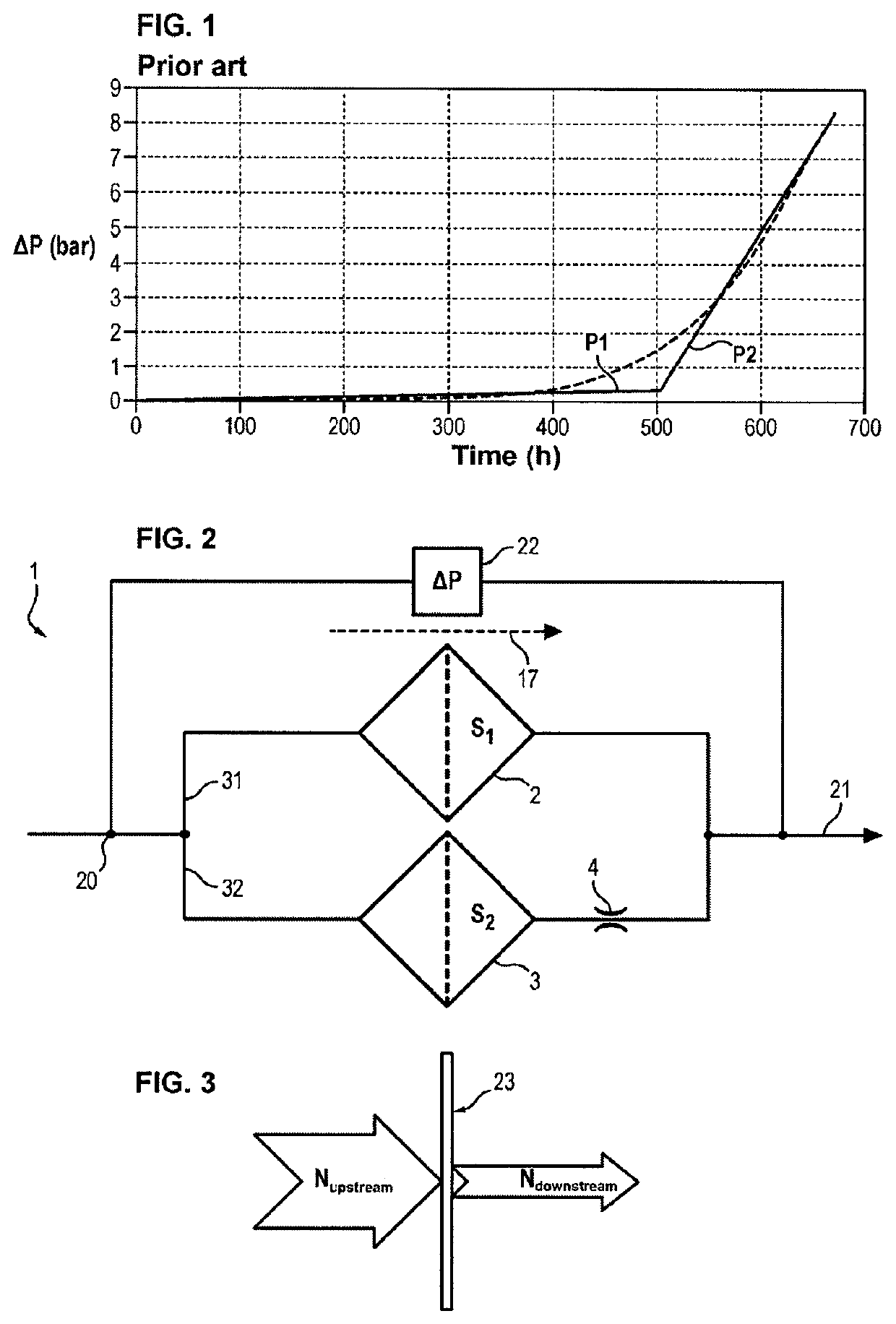
[0075]FIG. 2 represents an embodiment of a particle filter device 1 for the filtration of a fluid. The fluid is typically a liquid used in aeronautical circuits, for example in fuel circuits, lubricating oil, or hydraulic control oil.

[0076]The filter device 1 comprises a fluid inlet 20, a fluid outlet 21, a first fluid flow circuit 31 connecting the fluid inlet 20 to the fluid outlet 21 and a second fluid flow circuit 32 connecting the fluid inlet 20 to the fluid outlet 21. In addition, the first fluid flow circuit 31 comprises a first filter zone 2, and the second fluid flow circuit 32 comprises a second filter zone 3 and a constriction 4 having a given constant hydraulic resistance.

[0077]“hydraulic resistance” designates the ratio between the fluid pressure difference created by the constriction 4 between the upstream and downstream of the constriction 4 and the volume flow rate of fluid circulating through the constriction 4. By “constant” is meant th...


PUM

PropertyMeasurementUnit
particle sizeaaaaaaaaaa

Abstract

The invention relates to a particle filter device (1) comprising:a fluid inlet (20),a fluid outlet (21),a first fluid flow circuit (31) comprising a first filter zone (2) having a first filter surface (S1),a second fluid flow circuit (32) comprising a second filter zone (3) having a second filter surface (S2) and a constriction (4) having a constant hydraulic resistance so that, in operation, a first portion of the fluid flows through the first flow circuit (31) by passing through the first filter zone (2) and a second portion of the fluid flows through the second flow circuit (32) by passing through the second filter zone (3) and the constriction (4), and the first filter zone (2) reaches a predetermined clogging condition before the second filter zone (3).

Description

FIELD OF THE INVENTION[0001]The invention relates to a particle filter device and system. In addition, the invention relates to a method for monitoring the clogging condition of a particle filter device.TECHNOLOGICAL BACKGROUND[0002]It is known to filter a fluid by means of a particle filter device.[0003]For this purpose, the filter device generally comprises a filter cartridge comprising one or several filter zone(s) formed by one or several medium / media having a porous structure for retaining the particles present in said fluid.[0004]Over time, the filter zones(s) of the device become eventually clogged. These filter zones must be then cleaned or replaced.[0005]Moreover, in order to be able to carry out the maintenance operations, it may be necessary to know the evolution of the clogging condition of the filter device.[0006]When a particle filter device becomes clogged, the difference in the total pressures between the upstream and downstream ΔP of the filter device increases as t...

Claims


Application Information

Patent Timeline
Patent Type & Authority Patents(United States)
IPC IPC(8): B01D35/143B01D29/52B01D29/60B01D35/157B01D29/54B01D29/15B01D29/23B01D29/21
CPCB01D35/143B01D29/15B01D29/21B01D29/23B01D29/52B01D29/54B01D29/603B01D29/606B01D29/608B01D35/157B01D35/1576
Inventor MARTIN, JÉRÔMEPINON, RALUCA-LILIANAMASSONNAUD, ADRIEN
Owner SAFRAN FILTRATION SYST
Why Eureka
Try Eureka