Work bench

a technology for work benches and work surfaces, applied in work benches, vehicle components, supplementary fittings, etc., can solve problems such as unbalanced material work, and achieve the effect of convenient storage and setting up and disassembly

Active Publication Date: 2021-05-11
REYNOLDS GREG
View PDF21 Cites 0 Cited by
  • Summary
  • Abstract
  • Description
  • Claims
  • Application Information

AI Technical Summary

Benefits of technology

[0003]In accordance with the present invention, there is provided a work bench which is easily disassembled for storage or moving to a new location and may be adapted for use in various embodiments. The work bench of this invention may be altered to be used in several versions, i.e., a wall mounted version, a freestanding version and a tailgate version. One of the preferred embodiments of this invention is the wall mounted version. A pair of work bench support frames are connected to a vertical surface using fasteners or by a pair of standards spaced apart from one another and directly mounted to the vertical surface. The wall mounted version of the work bench, as well as the other embodiment, is constructed of a durable material, such as steel. The wall standards are preferably flat shaped with repeating clips allowing the work bench frames to hang therefrom. The repeating clips allow for the vertical adjustment of the work bench frames to the desired height. The wall mount standards may be attached to the wall or other vertical surface in any convenient manner. Keyhole slots allow for easy removal of the support frames or standards to a different location or to storage.
[0007]It is therefore the general object of the present invention to provide a work bench which may be sufficiently versatile to be used in different environments.
[0009]Yet another object of the present invention is providing a work bench that is easy to set up and disassemble for storage in a small space.

Problems solved by technology

It is often the case that when using a work bench the working surface is not as large as the material to be worked on creating an awkward situation where the material being worked on is unbalanced.

Method used


Image

  • Work bench
  • Work bench
  • Work bench

Examples


Embodiment Construction

[0027]The present inventions now will be described more fully hereinafter with reference to the accompanying drawings, in which preferred embodiments of the invention are shown. This invention may, however, be embodied in many different forms and should not be construed as limited to the embodiments set forth herein; rather these embodiments are provided so that this disclosure will be thorough and complete and will fully convey the scope of the invention to those skilled in the art. Like numbers refer to the elements throughout.

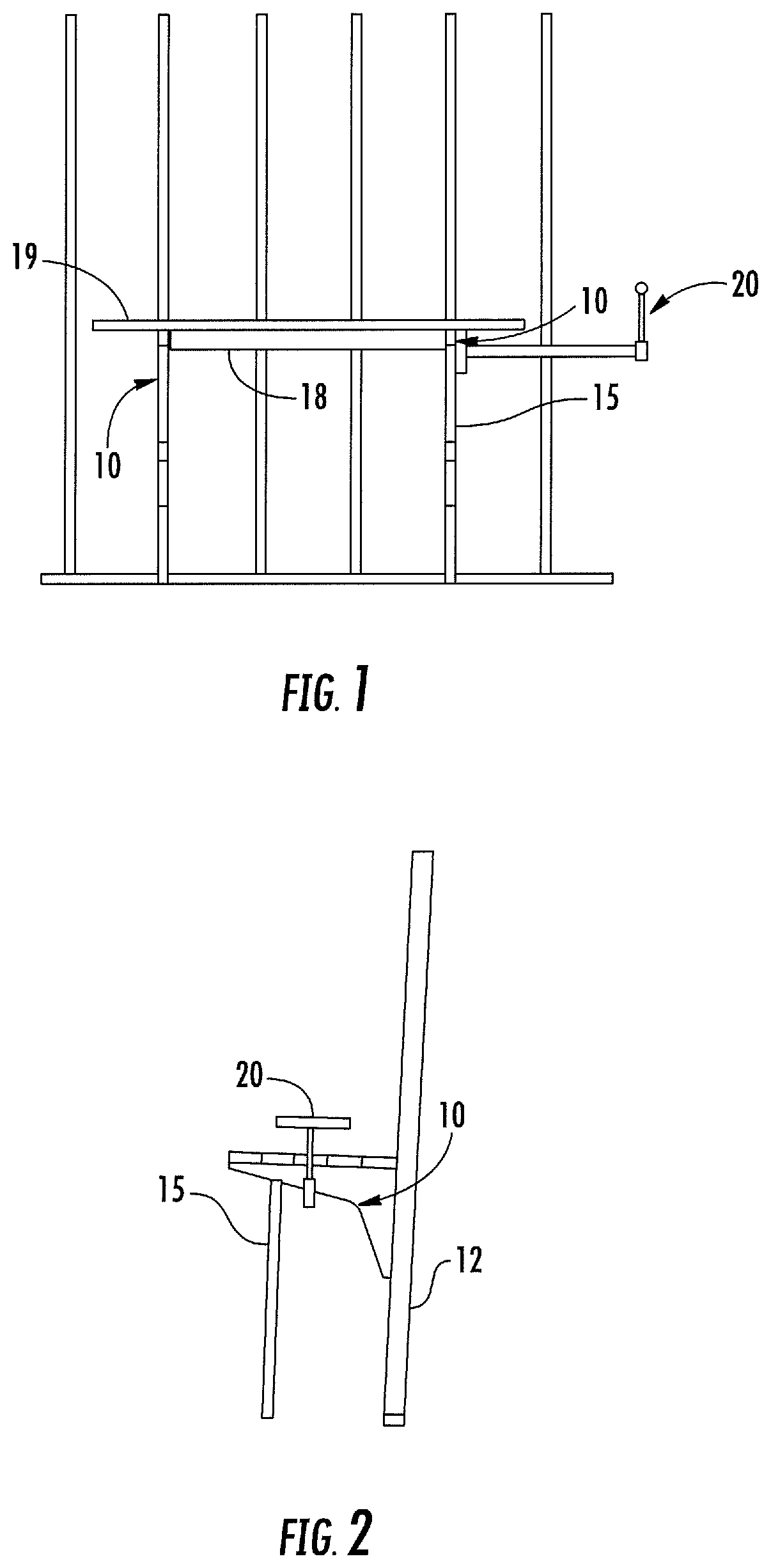
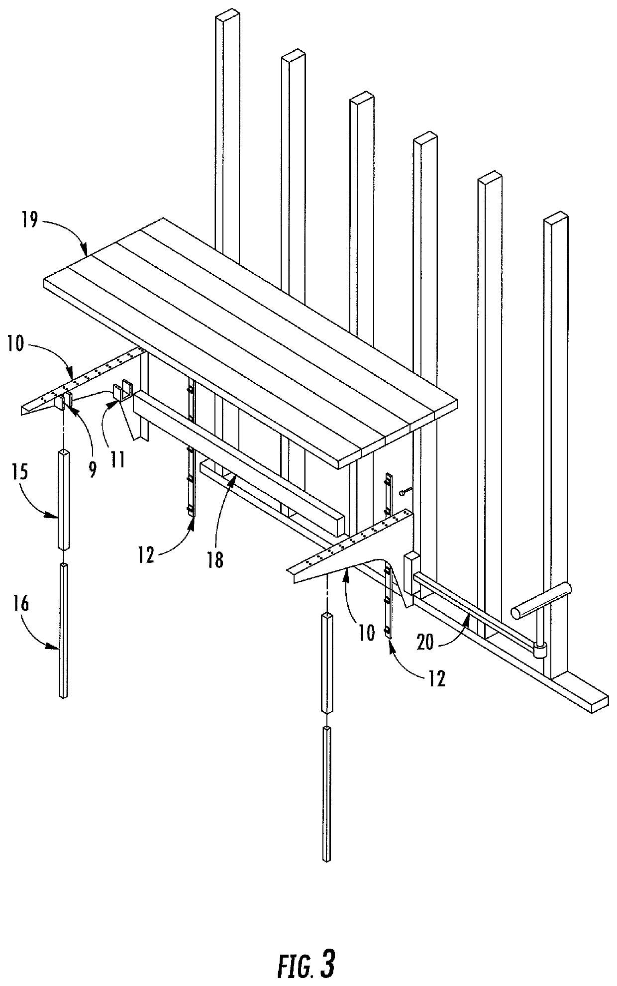
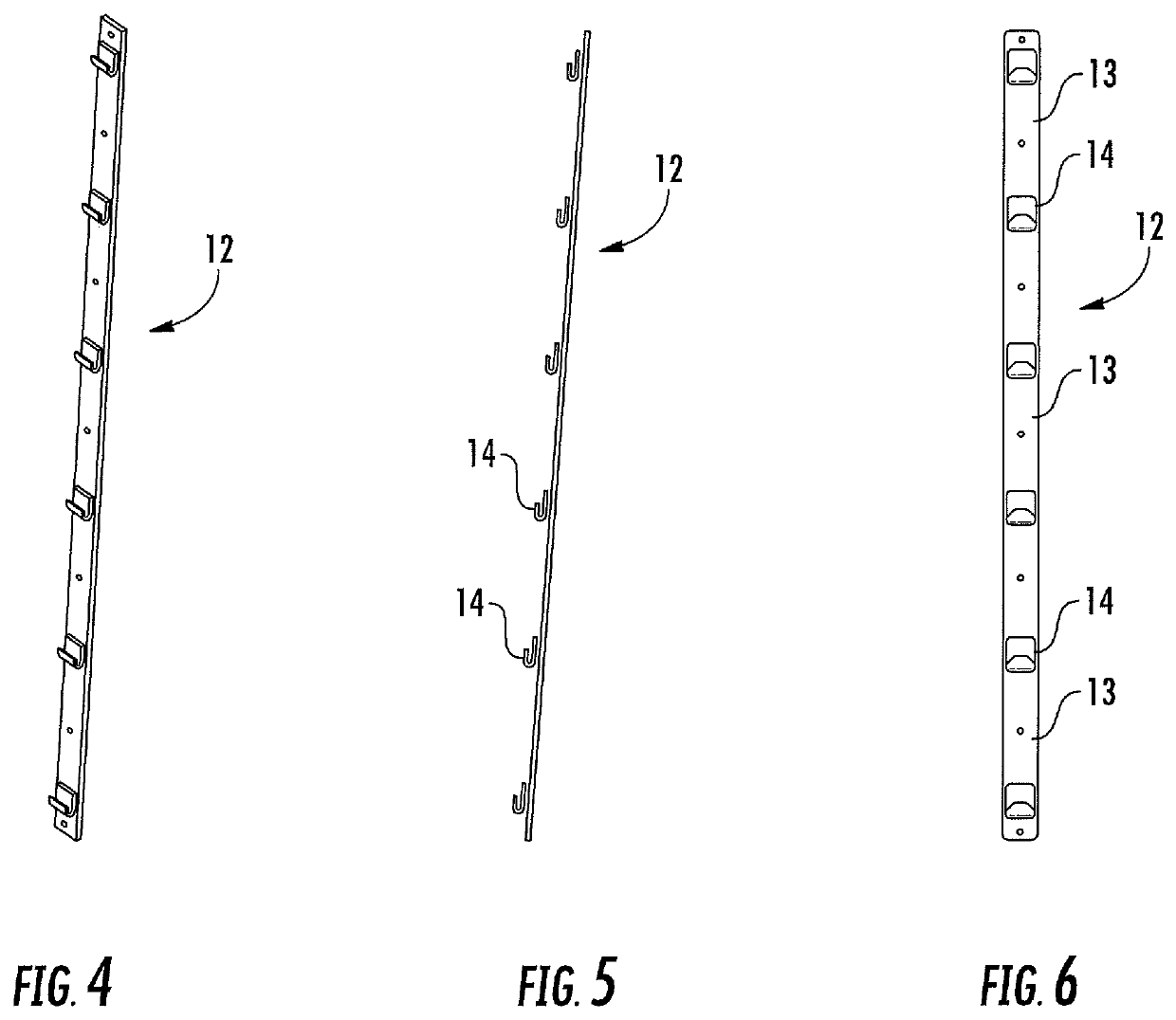
[0028]The modular work bench of this invention is found in a variety of embodiments. One of the preferred embodiments is the wall mounted version. The frames 10 of the wall mounted embodiment are shown in FIG. 1 in an assembled condition mounted to the studs of a wall. In FIG. 3 the wall mounted work bench frames 10 are shown in an unassembled condition. The frames 10 are constructed of a durable material, preferably steel. To connect frame 10 to a wall, a w...


PUM


Abstract

A work bench which is easily disassembled for storage or moving to a new location and may be used as a wall mounted version, a freestanding version and a tailgate version. A workbench frame is connected to a support surface by a pair of mounting standards spaced apart from one another and mounted to the support surface. The mount standards allow for the vertical adjustment of the workbench frame to the desired height. The workbench frame comprises a frame connector and a table top support flange. The work bench frames are the supports for the bench work surface. The table top support is a flange with holes to allow for connection to the work surface. Atop of the table angle top is a work surface. There is also provided a bench support extension connected to the work bench used as a support for material larger than the work surface.

Description

BACKGROUND OF THE INVENTION1. Field of the Invention[0001]The present invention relates to work benches. More specifically, this invention relates to a modular work bench that may be modified to be used in a variety of ways, such as attached to a wall, freestanding or attached to the tailgate of a vehicle and easily disassembled for storage and transportation.2. Description of Related Art[0002]Broadly speaking, a workbench is essentially a table that is sufficiently strong to support a workpiece or device for a user to work on. Historically work benches have been designed for specific uses such as for sawing or planing wood which a cabinetmaker might use. Other work benches are designed for other specific purposes which are as imaginative as any particular need. While there are a variety of work benches available most are as stationary or cumbersome as they are bulky and / or designed to be used in a single location or for a singular purpose. For example, where the workbench is a wall...

Claims


Application Information

Patent Timeline
Patent Type & Authority Patents(United States)
IPC IPC(8): B25H1/04B25H1/16B60R9/06
CPCB25H1/04B25H1/16B60R9/06
Inventor REYNOLDS, GREG
Owner REYNOLDS GREG
Why Eureka
Try Eureka