Locking electrical adaptor

a technology of electrical adaptors and electrical cords, applied in the direction of coupling contact members, coupling device connections, two-part coupling devices, etc., can solve the problems of increasing risk, opening the circuit, disrupting utility usage, frustrating and labor-intensive, etc., and achieves the effect of reducing the strain on the electrical cord and being readily manufactured

Active Publication Date: 2021-05-11
EDWARDS WILLIAM
View PDF24 Cites 2 Cited by
  • Summary
  • Abstract
  • Description
  • Claims
  • Application Information

AI Technical Summary

Benefits of technology

[0007]It is therefore an object of the present invention to provide a locking electrical adaptor for maintaining an electrical connection between the locking electrical adaptor and an electrical outlet, such as a wall outlet, for use of an electrical utility. The present invention provides an effective means to secure an electrical adaptor within a wall outlet, such that various forces, such as gravity, pulling, and lateral forces, do not disrupt the connection and circuit.
[0009]In some embodiments, the biased grounding prong is monolithic with the lip. In such embodiments, the biased grounding prong is a single piece of material and is structurally continuous. Such embodiments may be advantageous for simplification of manufacture and use of the locking electrical adaptor, and additionally, may require no additional or separate structure affixed to the biased grounding prong for use of the locking mechanism.
[0011]In some embodiments, the elongated strip includes an upper portion connected to a lower portion by a U-shaped forward end of the elongated strip. In such embodiments, the elongated strip includes a lateral gap on a medial portion thereof, such that the upper portion lies above or adjacent to the lower portion, and the lateral gap is between the upper portion and the lower portion. The lateral gap provides a space for a flexible movement of the elongated strip, as may occur during insertion into and removal from the electrical outlet.
[0014]In some embodiments, the lip comprises a rearward vertical wall and a forward sloped wall. Such a structure may be advantageous for effectively locking the adaptor within the outlet, and for effectively unlocking the adaptor from the outlet for removal. The rearward vertical wall engages the ridge of the outlet in the locked configuration and does not engage the ridge of the outlet in the unlocked configuration.
[0017]In some embodiments, the housing further comprises an electrical cord that extends upward from an upper surface of the housing. In certain of such embodiments, the housing may be configured for use with an outlet that is installed upside down within a wall, such that a grounding prong aperture of the outlet is positioned above a pair of current prong apertures of the outlet. In this manner, the button may be positioned upward for easy visualization before, during, and after use of the button, and a strain on the electrical cord may be minimized because the upper surface of the housing may be positioned downward such that the electrical cord drapes downward with the force of gravity.
[0018]Another object of the present invention is to provide a locking electrical adaptor that may be readily manufactured from materials that permit relative economy and are commensurate with durability.

Problems solved by technology

These movements can contribute to an increased risk of the adaptor becoming disengaged from the outlet, which opens the circuit and disrupts usage of the utility.
These interruptions can be frustrating and labor-intensive, and can lead to mistakes made when using the utility.
In addition, some outlets may be positioned at an odd angle, such as on a ceiling or other structure, such that use of the outlet may be difficult or impossible in view of the adaptor persistently falling out of the outlet or otherwise becoming loose such that the circuit is opened.
These devices are often difficult to use, and unsatisfactory in the sense that they do not effectively reduce the probability of the adaptor opening a circuit or falling out of the outlet.

Method used


Image

  • Locking electrical adaptor
  • Locking electrical adaptor
  • Locking electrical adaptor

Examples


first embodiment

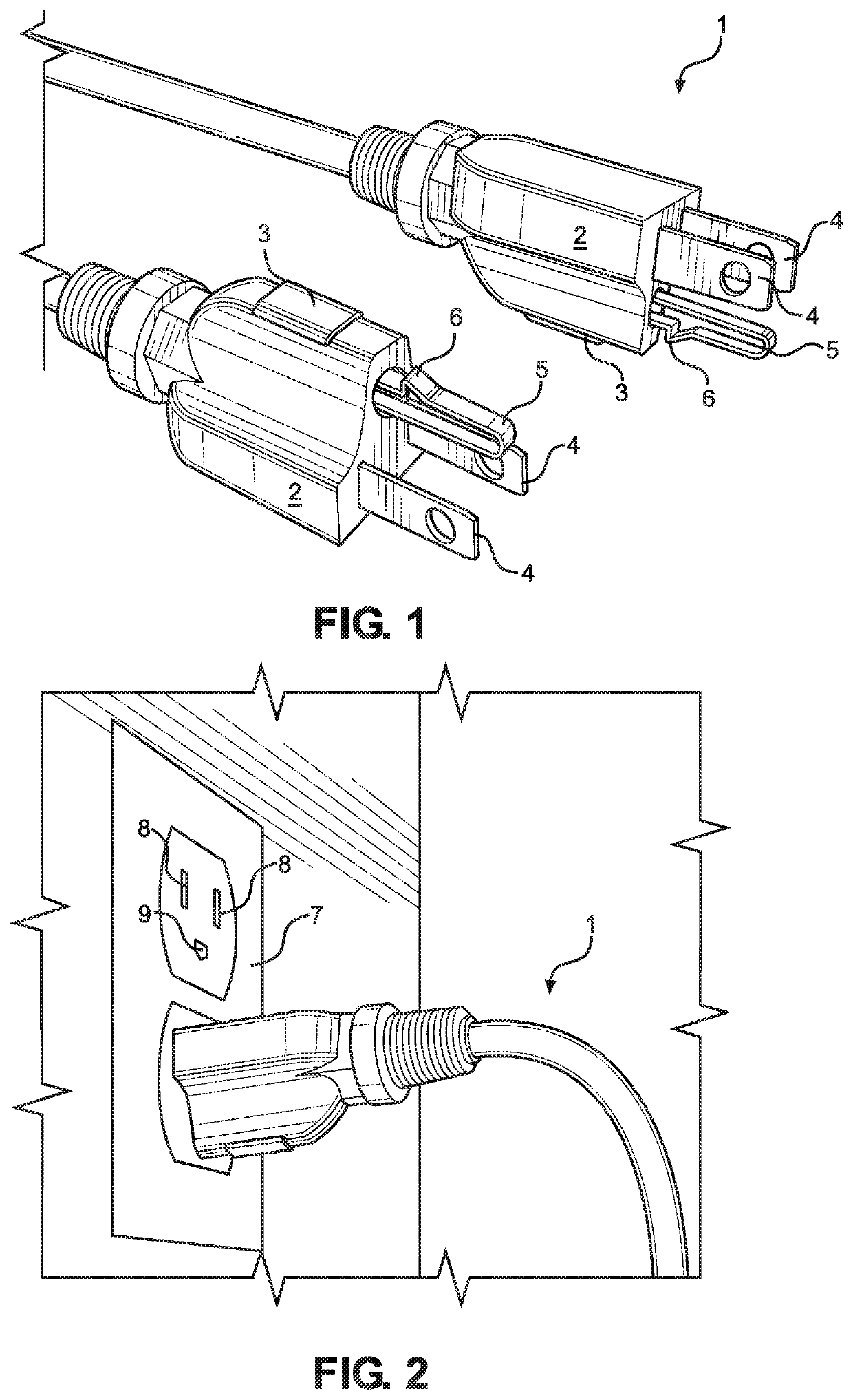
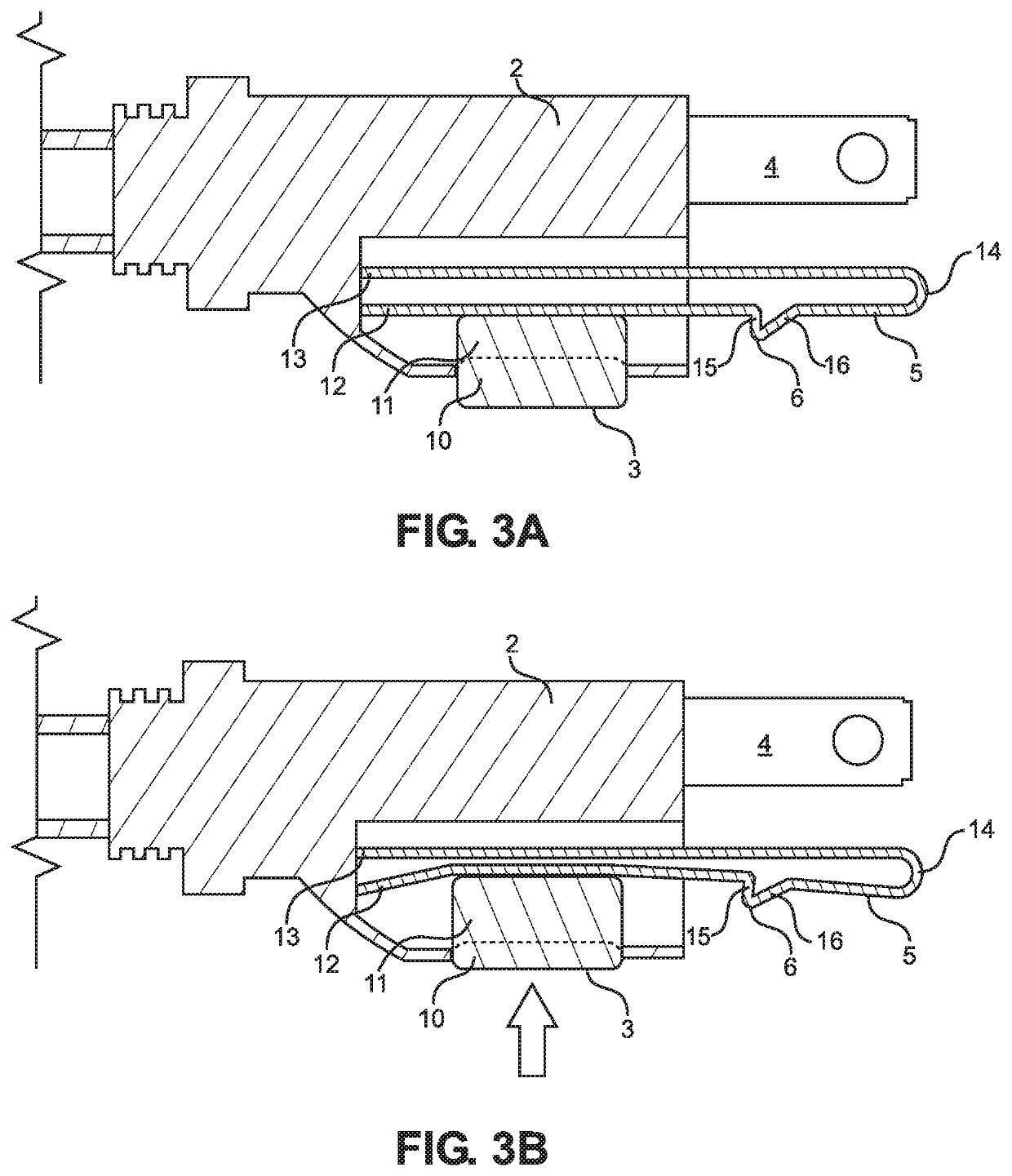
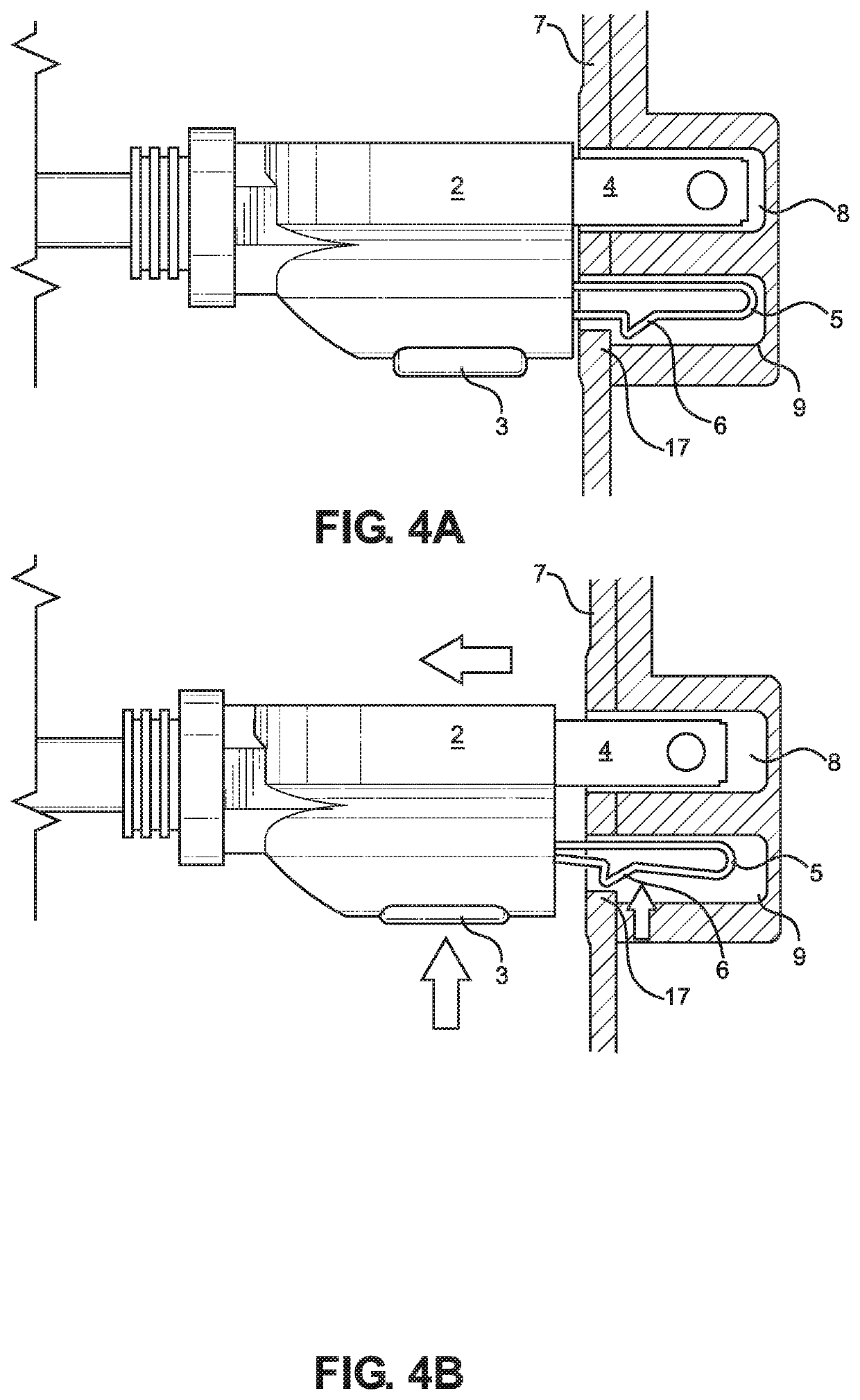
[0034]Referring now to FIGS. 1, 2, 3A, 3B, 4A, and 4B, there are depicted several views of a locking electrical adaptor according to the present invention. In the shown embodiment, the locking electrical adaptor 1 includes a housing 2 with an electrical cord that extends rearward from a rearward surface of the housing 2. The rearward-extending electrical cord may be advantageous for maximizing a range of motion of a utility attached thereto during use, and may also be helpful with regular use, e.g., regular locking and unlocking of the adaptor 1 with respect to an electrical outlet 7. In addition, because the electrical cord extends straight out of the rearward surface of the housing 2 and is perpendicular to the electrical outlet 7 when inserted thereto, such embodiments may be beneficial for use with electrical outlets positioned on ceilings or other irregularly angled configurations. In this manner, a weight of the cord may not disfigure or disconnect one or more prongs of the ad...

second embodiment

[0035]FIGS. 5, 6, 7A, 7B, 8A, and 8B depict several views of the locking electrical adaptor. In the shown embodiment, the locking electrical adaptor 1 includes a housing 2 with an electrical cord that extends upward from an upper surface of the housing 2. In these figures the electrical cord is depicted as extending upward, and the electrical outlet 7 is depicted as installed upright within the wall, for consistent presentation of the present invention. However, it should be understood that some electrical outlets are installed upside down within the wall, such that a grounding prong aperture 9 of the outlet 7 is positioned above a pair of current prong apertures 8 of the outlet 7, as would be understood by a person having ordinary skill in the art. In this manner, such embodiments of the adaptor 1 may be advantageous for use with upside down outlets 7. In addition, in such embodiments, the cord would extend downward, with the force of gravity. In this manner, a stress or strain on ...


PUM


Abstract

A locking electrical adaptor. The adaptor includes a housing with a pair of conductive prongs for carrying an electrical current, and a grounding prong for grounding an electrical connection of the pair of conductive prongs. The grounding prong is comprised of a flexible conductive material, and includes a lip on a portion thereof, such that upon insertion of the adaptor into an electrical outlet, the lip snaps into place behind a ridge of the electrical outlet to secure the adaptor thereto and lock it in place. The adaptor may be unlocked by depressing a button disposed on the housing, which bends the grounding prong and displaces the lip. After the adaptor is unlocked, the adaptor may be removed from the electrical outlet.

Description

CROSS REFERENCE TO RELATED APPLICATIONS[0001]This application claims priority under 35 U.S.C. § 119(e) to U.S. Provisional Application No. 62 / 758,087 filed on Nov. 9, 2018. The above identified patent application is incorporated by reference herein in its entirety to provide continuity of disclosure.BACKGROUND OF THE INVENTION[0002]The present invention relates to a locking electrical adaptor for securing an electrical connection between the adaptor and an electrical outlet.[0003]An electrical adaptor is inserted into an electrical outlet to complete a circuit such that a current of the circuit is transmitted through a utility connected to the adaptor, for use of the utility. Many such utilities may require movement to operate the utility, such as rolling a vacuum cleaner, operating a floor buffer, using a power drill at various positions within a space, and the like. These movements can contribute to an increased risk of the adaptor becoming disengaged from the outlet, which opens ...

Claims


Application Information

Patent Timeline
Patent Type & Authority Patents(United States)
IPC IPC(8): H01R13/627H01R13/635H01R13/20H01R24/30H01R103/00
CPCH01R13/6272H01R13/20H01R13/635H01R24/30H01R2103/00H01R13/652
Inventor EDWARDS, WILLIAM
Owner EDWARDS WILLIAM
Why Eureka
Try Eureka