
Backlight module

Active Publication Date: 2021-05-18
NANO PRECISION TAIWAN LTD
View PDF10 Cites 0 Cited by
  • Summary
  • Abstract
  • Description
  • Claims
  • Application Information

AI Technical Summary

Benefits of technology

The patent makes a better backlight module for display screens. It works by adding microstructures to the optical film between the prism sheet and light guide plate, which increases the amount of light emitted at an angle close to the normal viewing angle. This improves the efficiency with which the backlight collects light. Additionally, by adding a diffusion layer on the other side of the optical film, the backlight module is better at concealing its components. This makes it easier to assemble and adjust the components in the backlight module, which increases the yield rate of the overall assembly.

Problems solved by technology

However, the backlight module configured with double brightness enhancement films has limitation in achieving slim design of the backlight module.
However, from another point of view, in use of the light-collecting backlight module, when there are small defects or tiny objects (such as dusts or shavings that are brought in during assembly) between the film layers of the backlight module, they are easily detected in the process of the optical inspection of the following quality control.
In other words, the backlight module with excellent light collecting efficiency has poor concealing ability to prevent small defects, which results in a decrease in overall assembly yield rate.
Therefore, how to balance the light collecting efficiency and concealing ability of the backlight module is one of the problems that manufacturers need to face when designing and developing the product.

Method used


Image

  • Backlight module
  • Backlight module
  • Backlight module

Examples


first embodiment

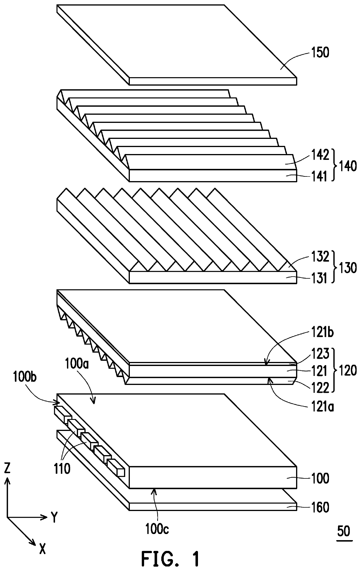
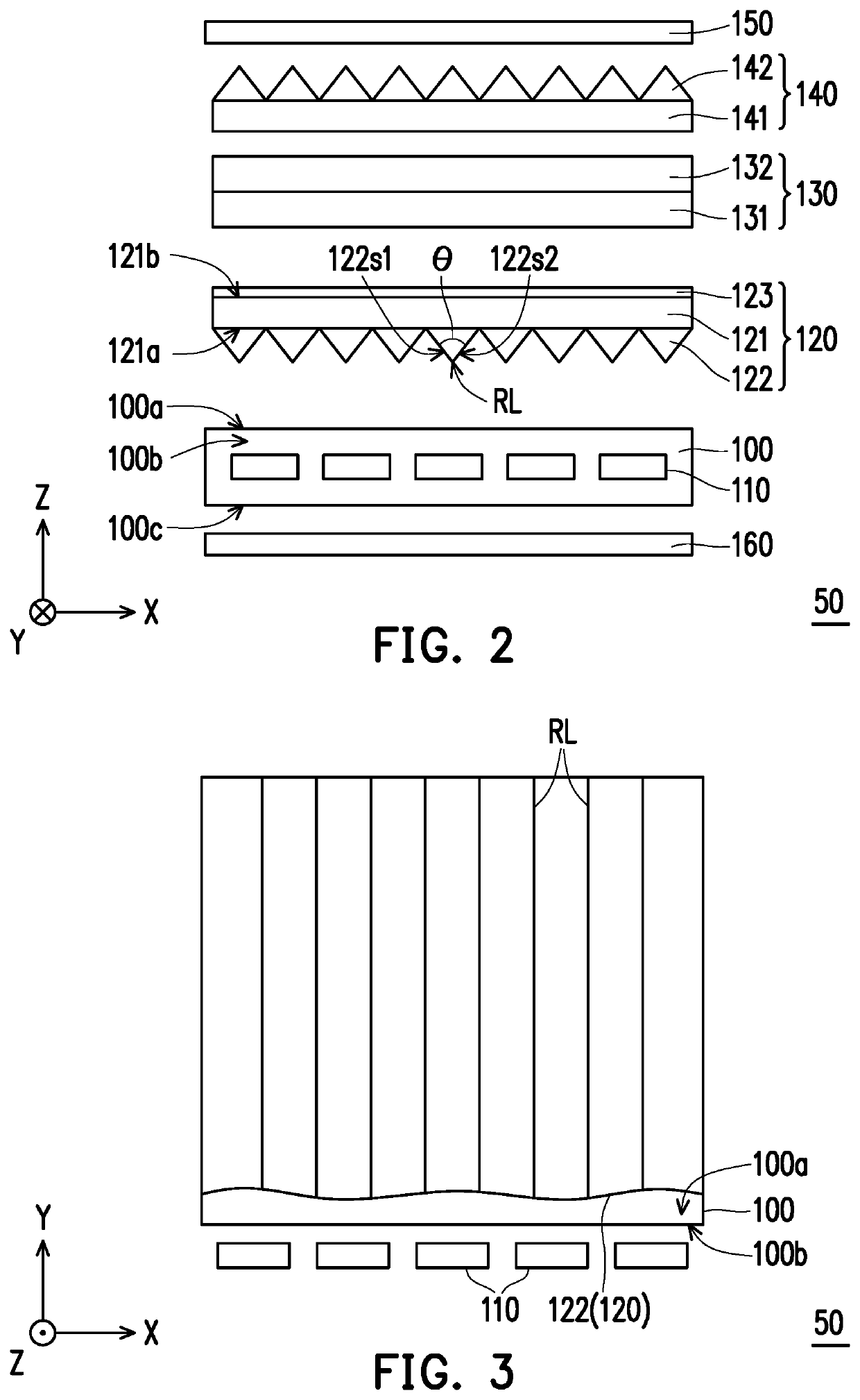
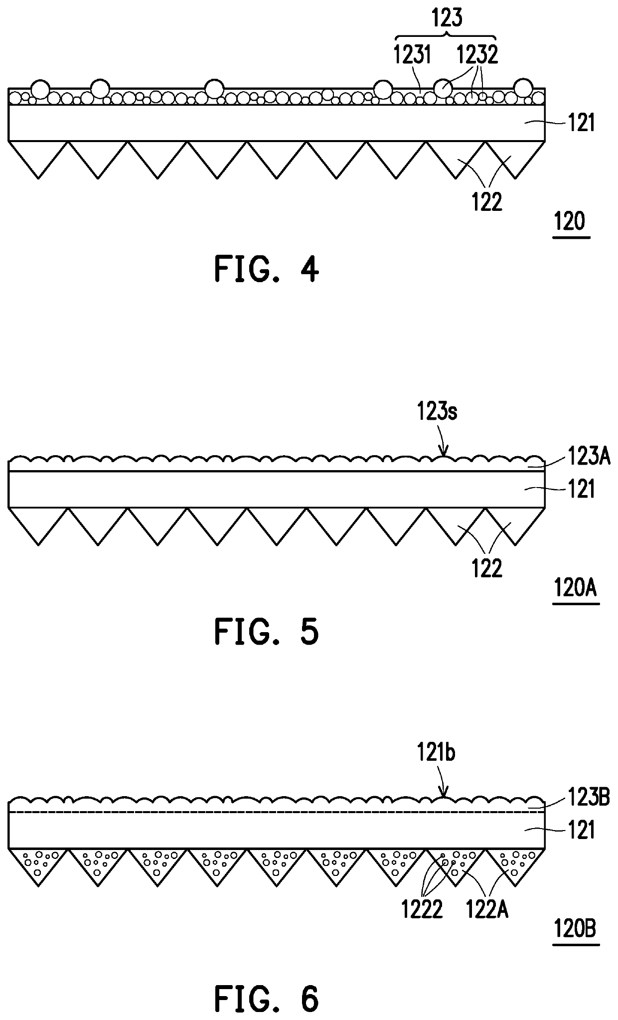
[0035]FIG. 1 is a schematic view of a backlight module of the disclosure. FIG. 2 is a schematic side view of the backlight module of FIG. 1. FIG. 3 is a schematic top view of the backlight module of FIG. 1. FIG. 4 is a schematic cross-sectional view of the optical film of FIG. 1. Specifically, FIG. 3 only illustrates a light guide plate 100, a light source 110, and an optical microstructure 122 of FIG. 2 for clarity of presentation.

[0036]Referring to FIG. 1 and FIG. 2, a backlight module 50 includes a light guide plate 100, a light source 110, and an optical film 120. The light guide plate 100 has a light emitting surface 100a and a light incident surface 100b, and the light emitting surface 100a is connected to the light incident surface 100b. The optical film 120 is overlapped with the light emitting surface 100a of the light guide plate 100. The light source 110 is disposed on one side of the light incident surface 100b of the light guide plate 100. That is, the backlight module ...

sixth embodiment

[0055]FIG. 11 is a schematic view of a backlight module according to the disclosure. FIG. 12 is a schematic side view of the backlight module of FIG. 11. FIG. 13 is a schematic cross-sectional view of the second prism sheet of FIG. 11. Referring to FIG. 11 to FIG. 13, the difference between the backlight module 50C of the embodiment and the backlight module 50 of FIG. 1 lies in the configuration of the second prism sheet. In the embodiment, the second prism sheet 140A further has a second diffusion structure layer 143 disposed on a side of the second prism sheet 140A facing the first prism sheet 130, and overlapped with a plurality of prism structures 142 in the direction Z.

[0056]For example, referring to FIG. 13, the second diffusion structure layer 143 of the second prism sheet 140A may selectively include a photosensitive adhesive layer 1431 and a plurality of diffusion particles 1432, wherein the diffusion particles 1432 are covered by the photosensitive adhesive layer 1431 (as ...


PUM


Abstract

A backlight module including a light guide plate, a light source, an optical film, a first prism sheet and a second prism sheet is provided. The light guide plate has a light incident surface and a light emitting surface. The light source is disposed on a side of the light incident surface. The optical film is overlapped with the light emitting surface and includes a substrate, a plurality of optical microstructures and a first diffusion structure layer. The optical microstructures are disposed on a light incident side of the substrate. An extending direction of the optical microstructures intersects with the light incident surface. The first diffusion structure layer is disposed on a light emitting side of the substrate and is overlapped with the optical microstructures. The first prism sheet and the second prism sheet are overlapped with the optical film and are positioned on the light emitting side.

Description

CROSS-REFERENCE TO RELATED APPLICATION[0001]This application claims the priority benefit of China application serial no. 201910455238.6, filed on May 29, 2019, and Taiwan application serial no. 108121955, filed on Jun. 24, 2019. The entirety of each of the above-mentioned patent applications is hereby incorporated by reference herein and made a part of this specification.BACKGROUNDTechnical Field[0002]The disclosure relates to an optical module, and more particularly to a backlight module.Description of Related Art[0003]Along with the widespread application of non-self-luminous displays such as liquid crystal display devices, the design of backlight modules needs to be adjusted for different scenarios. In order to improve the light energy utilization rate of light source, the backlight module equipped with Brightness Enhancement Film (BEF) has become one of the mainstreams in the market. In general, such backlight module is provided with a laminated structure of two brightness enhan...

Claims


Application Information

Patent Timeline
IPC IPC(8): F21V8/00G02B5/04
CPCG02B6/0025G02B5/045G02B5/0215G02B5/0226G02B5/0231G02B5/0242G02B5/0278G02B6/0051G02B6/0053G02B6/0055
Inventor LI, CHING-HSIANGYANG, SHU-PINGSU, FANG-HSUAN
Owner NANO PRECISION TAIWAN LTD
Learn More