
Directional illumination apparatus and privacy display

a technology of illumination apparatus and privacy display, which is applied in the direction of lighting and heating apparatus, semiconductor devices for light sources, instruments, etc., can solve the problems of high cost of individual optics alignment, low cost, and limited privacy function of display, so as to reduce device thickness and low cost. , the effect of low cos

Active Publication Date: 2021-05-25
REALD SPARK LLC
View PDF103 Cites 26 Cited by
  • Summary
  • Abstract
  • Description
  • Claims
  • Application Information

AI Technical Summary

Benefits of technology

[0015]Advantageously a thin directional illumination apparatus may be provided with low surface profile variations. Widely spaced LEDs may be provided over a large area while achieving high image uniformity. Cost and complexity of manufacture may be reduced. High brightness may be achieved.
[0041]Advantageously the illumination apparatus may be provided with increased stability of alignment between the reflective surface and the LEDs of the array of LEDs.

Problems solved by technology

A privacy function may be provided by micro-louvre optical films that transmit a high luminance from a display in an on-axis direction with low luminance in off-axis positions, however such films are not switchable, and thus the display is limited to privacy only function.
Such an edge illuminated light guide plate is not typically appropriate for two-dimensional local dimming for HDR-LCD illumination, or free-form shaped LCD.
Such backlights require expensive pick-and-place LED and individual optics alignment and have a high thickness and reduced efficiency in comparison to edge illuminated backlights.
Such sizes and tolerances prevent application to very high resolution displays.

Method used


Image

  • Directional illumination apparatus and privacy display
  • Directional illumination apparatus and privacy display
  • Directional illumination apparatus and privacy display

Examples


Embodiment Construction

[0142]A private mode of operation of a display is one in which an observer sees a low contrast sensitivity such that an image is not clearly visible. Contrast sensitivity is a measure of the ability to discern between luminances of different levels in a static image. Inverse contrast sensitivity may be used as a measure of visual security, in that a high visual security level (VSL) corresponds to low image visibility.

[0143]For a privacy display providing an image to an observer, visual security may be given as:

VSL=(Y+R) / (Y−K)  eqn. 1

[0144]where VSL is the visual security level, Y is the luminance of the white state of the display at a snooper viewing angle, K is the luminance of the black state of the display at the snooper viewing angle and R is the luminance of reflected light from the display.

[0145]Panel contrast ratio is given as:

C=Y / K  eqn. 2

[0146]For high contrast optical LCD modes, the white state transmission remains substantially constant with viewing angle. In the contrast...


PUM

PropertyMeasurementUnit
angleaaaaaaaaaa
angleaaaaaaaaaa
angleaaaaaaaaaa

Abstract

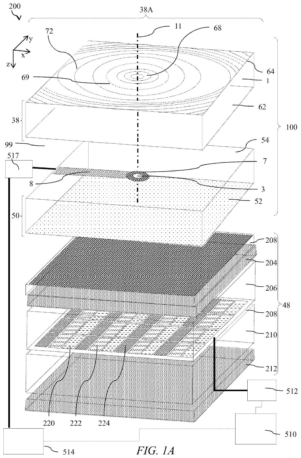
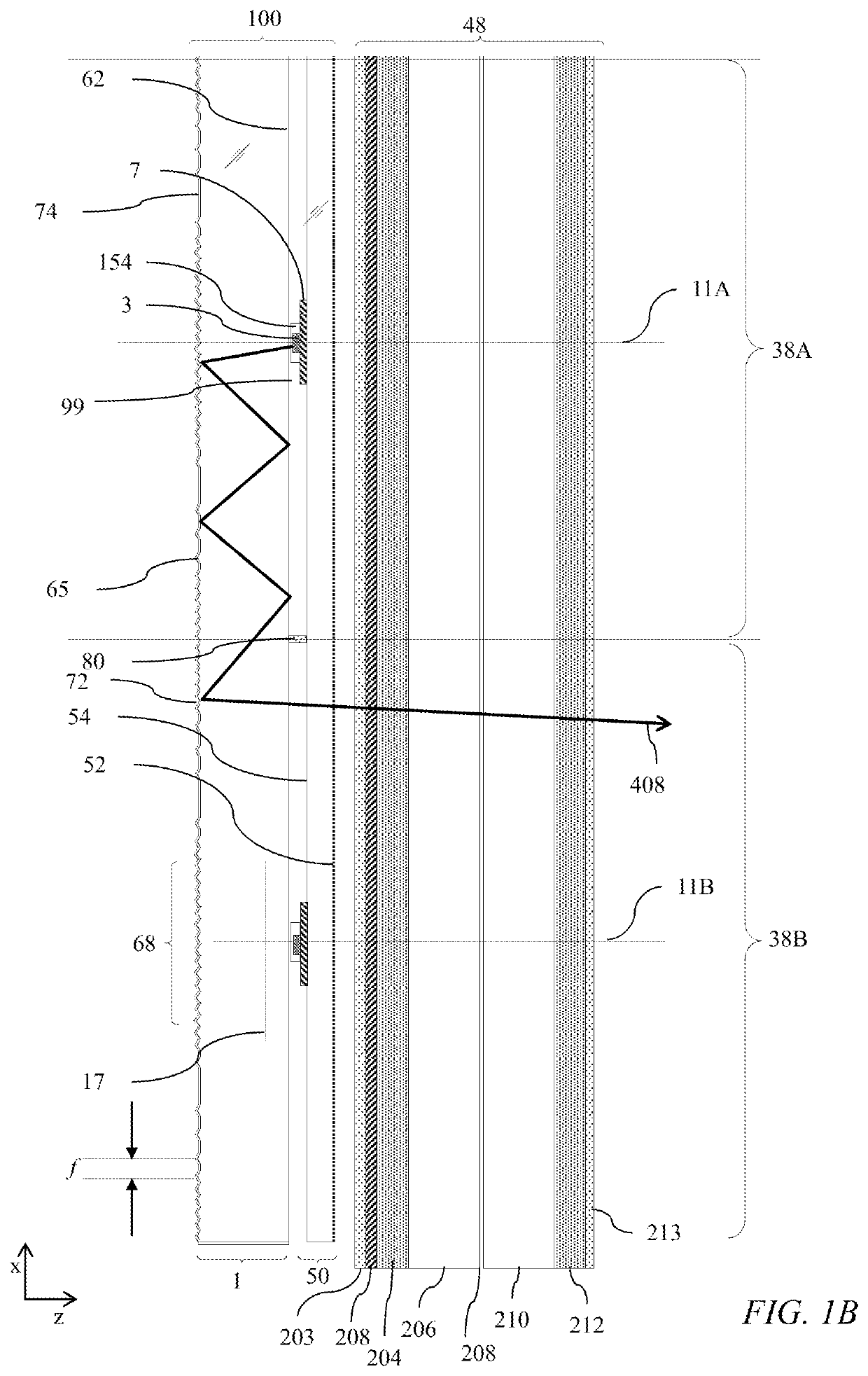
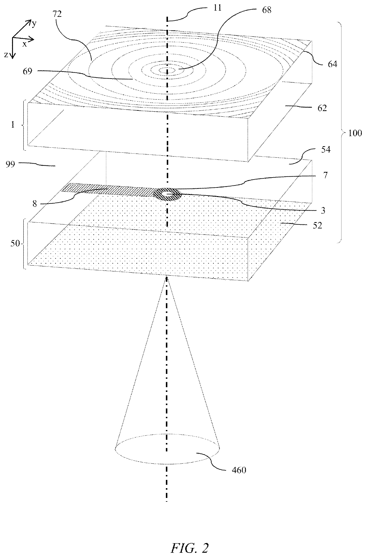
A directional illumination apparatus comprises a waveguide with a reflective surface comprising reflective pairs of light input facets, reflective light extraction facets and an output transmissive surface. An array of micro-LEDs is arranged to illuminate the reflective surface in a rearwards direction. The pairs of light input facets direct light within the waveguide and reflective light extraction facets cooperate to provide a uniform output illumination across the output aperture of the waveguide with collimated light. A thin and efficient illumination apparatus may be used for high dynamic range display backlighting, privacy display or environmental illumination applications.

Description

TECHNICAL FIELD[0001]This disclosure generally relates to illumination from light modulation devices, and more specifically relates to optical stacks for providing narrow angle illumination for use in display including privacy display, high dynamic range display and for use in environmental illumination.BACKGROUND[0002]Privacy displays provide image visibility to a primary user that is typically in an on-axis position and reduced visibility of image content to a snooper, that is typically in an off-axis position. A privacy function may be provided by micro-louvre optical films that transmit a high luminance from a display in an on-axis direction with low luminance in off-axis positions, however such films are not switchable, and thus the display is limited to privacy only function.[0003]Switchable privacy displays may be provided by control of the off-axis optical output from a spatial light modulator. Control may be provided by means of off-axis luminance reduction, for example by ...

Claims


Application Information

Patent Timeline
Patent Type & Authority Patents(United States)
IPC IPC(8): G02F1/1335G02F1/13357H01L33/60F21K9/68F21K9/64
CPCG02F1/133605F21K9/64F21K9/68G02F1/133603H01L33/60H01L25/0753G02F1/133607G02B6/0035G02B6/0058G02B6/0068G02B6/0073G02B6/0091
Inventor ROBINSON, MICHAEL G.WOODGATE, GRAHAM J.
Owner REALD SPARK LLC
Learn More