Eureka AIR delivers breakthrough ideas for toughest innovation challenges, trusted by R&D personnel around the world.

Triggered generation of nulling signals to null an RF beam using a detachable nulling subassembly

Active Publication Date: 2021-06-01
SOFTBANK CORP
View PDF19 Cites 1 Cited by
  • Summary
  • Abstract
  • Description
  • Claims
  • Application Information

AI Technical Summary

Benefits of technology

The patent describes a system for modifying the beamforming signal of a primary antenna system on a high-altitude platform (HAP) using a detachable nulling subassembly. This subassembly includes multiple antenna elements that can be activated or deactivated through a nulling activation switch. The detachable nulling subassembly can be easily attached or detached from the primary antenna system before the HAP launches for a particular mission. The activation or deactivation of the nulling elements can modify the antenna pattern footprint of the primary antenna system, resulting in a smaller beam pattern that only extends a certain distance in a particular direction. This can help improve the efficiency and accuracy of the communication system. The method also includes determining the result of the beamforming signal and generating the nulling signals based on the RF signal.

Problems solved by technology

In these situations, it is more likely to encounter interference, and likely reduce the coverage and capacity of the HAP.

Method used


Image

  • Triggered generation of nulling signals to null an RF beam using a detachable nulling subassembly
  • Triggered generation of nulling signals to null an RF beam using a detachable nulling subassembly
  • Triggered generation of nulling signals to null an RF beam using a detachable nulling subassembly

Examples


example networks

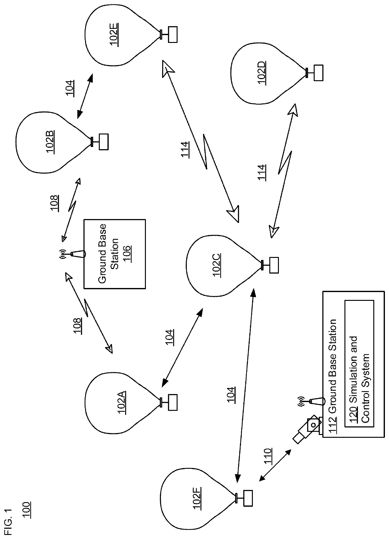
[0012]FIG. 1 depicts an example system 100 in which a fleet of balloons or other high altitude platforms described above may be used. This example should not be considered as limiting the scope of the disclosure or usefulness of the features described herein. System 100 may be considered a balloon network. In this example, balloon network 100 includes a plurality of devices, such as balloons 102A-F as well as ground base stations 106 and 112. Balloon network 100 may also include a plurality of additional devices, such as various devices supporting a telecommunication service (not shown) as discussed in more detail below or other systems that may participate in the network.

[0013]The devices in system 100 are configured to communicate with one another. As an example, the balloons may include communication links 104 and / or 114 in order to facilitate intra-balloon communications. By way of example, links 114 may employ radio frequency (RF) signals (e.g., millimeter wave transmissions) w...


PUM


Abstract

A method and apparatus are provided for nulling a radio frequency (RF) beam for a high-altitude platform (HAP). A transmitter generates an RF signal. A primary antenna system generates an RF beam based on the RF signal. One or more processors determine a result indicating whether to modify the RF beam. When the result indicates to modify the RF beam, a detachable nulling subassembly generates nulling signals based on the RF signal to modify the RF beam generated by the primary antenna system.

Description

BACKGROUND[0001]An antenna system in a high-altitude platform (HAP), such as a balloon, may provide coverage to a large area on the ground. Interference is of minimal concern when the HAP flies over sparsely populated regions. However, in some situations, the HAP may fly close to country borders or close to terrestrial communication towers. In these situations, it is more likely to encounter interference, and likely reduce the coverage and capacity of the HAP.BRIEF SUMMARY[0002]An antenna system including a detachable nulling subassembly may be provided in the HAP. The detachable notch element subassembly may include a plurality of notch antenna elements that may be individually activated and deactivated through the use of a nulling activation switch. The detachable nulling subassembly may be configured to easily attach and detach (or otherwise engage or disengage) to / from an interface of a primary antenna system, prior to the launch of the HAP for a particular mission.[0003]In part...

Claims


Application Information

Patent Timeline
IPC IPC(8): H01Q3/26H04B7/185
CPCH01Q3/2611H04B7/18504H04B7/2041H04B7/0695H04B7/0617
Inventor ANANTH, SHARATHBEHROOZI, CYRUSMORRIS, NEVIN
Owner SOFTBANK CORP
Why Eureka
Eureka Blog
Learn More