Main drive assembly positioning structure for throwing trap

a positioning structure and assembly technology, applied in the direction of moving targets, weapons, targets, etc., can solve the problems of relatively high manufacturing cost, relatively wasteful of manpower and assembly costs, cumbersome procedures, etc., and achieve the effect of saving assembly manpower and man-hours, simplifying the installation process, and reducing costs

Active Publication Date: 2021-06-15
LIU CHEH KANG
View PDF22 Cites 1 Cited by
  • Summary
  • Abstract
  • Description
  • Claims
  • Application Information

AI Technical Summary

Benefits of technology

[0005]The present invention has been accomplished under the circumstances in view. It is therefore the main object of the present invention to provide a main drive assembly positioning structure for throwing trap, which is so configured that the main drive assembly of the throwing trap can be pivoted and positioned through a first fixing frame and a second fixing frame, so that the main drive assembly positioning structure has the advantages of saving accessories (for example, the upper fixing frame, bearing seat and lower fixing frame can be relatively saved) and reducing costs.
[0006]It is another object of the present invention to provide a main drive assembly positioning structure for throwing trap, which can relatively simplify the installation process and save assembly manpower and man-hours.

Problems solved by technology

1. There are many accessories, such as the upper fixing frame 8, the lower fixing frame 9, and the bearing seat 7, and the manufacturing cost is relatively high.
2. Not only there are more accessories and the installation procedure is cumbersome, it is relatively wasteful of manpower and assembly costs.

Method used


Image

  • Main drive assembly positioning structure for throwing trap
  • Main drive assembly positioning structure for throwing trap
  • Main drive assembly positioning structure for throwing trap

Examples


Embodiment Construction

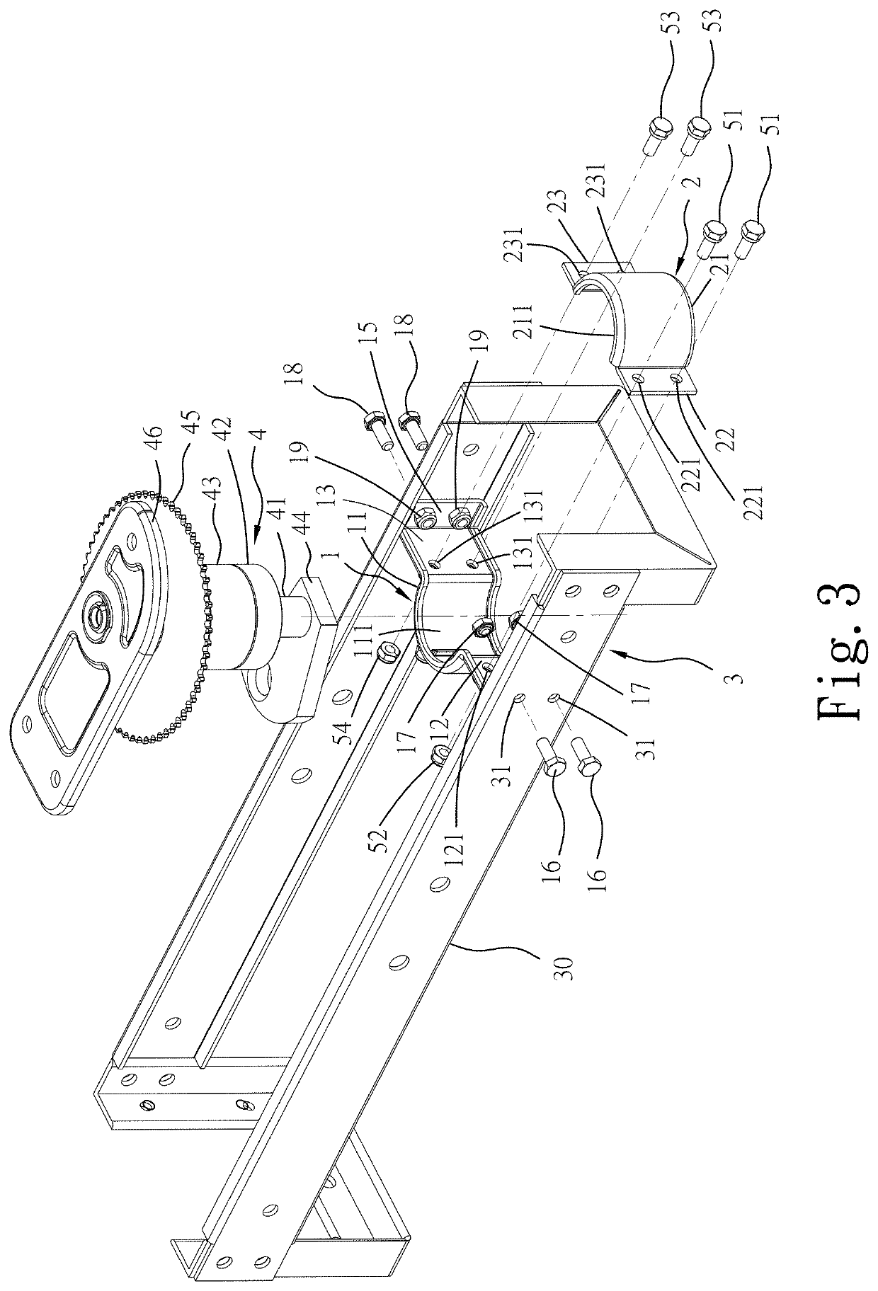
[0012]Referring to FIGS. 3 and 4, a main drive assembly positioning structure is used in a throwing trap 3 to pivotally position a main drive assembly 4 on a main frame 30 of the throwing trap 3. The main drive assembly 4 comprises a throwing arm drive spindle 41, a first bearing 42 and a second bearing 43 assembled on the throwing arm drive spindle 41, a prive plate 44 welded to the bottom end of the throwing arm drive spindle 41, a sprocket 45 assembled on the throwing arm drive spindle 41 above the first bearing 42 and the second bearing 43, an arm mounting plate 46 welded to the opposing top end of the throwing arm drive spindle 41, and a throwing arm mounted on the top side of the arm mounting plate 46. When the sprocket 45 of the main drive assembly 4 is driven to rotate, the throwing arm drive spindle 41 is relatively driven to rotate, so that the throwing arm rotates accordingly, and the clay (not shown) placed on the throwing arm is thrown out by centrifugal force.

[0013]The...


PUM


Abstract

A main drive assembly positioning structure for pivotally positioning a main drive assembly on a main frame of a throwing trap by attaching a first fixing frame with a first inner semicircular arc groove and a second fixing frame with a second inner semicircular arc groove to the left and right sides of the main drive assembly and using fastening members to affix the first fixing frame and the second fixing frame together, so that the main drive assembly positioning structure has the advantages of saving accessories and reducing costs and can relatively simplify the installation process and save assembly manpower and man-hours.

Description

BACKGROUND AND SUMMARY OF THE INVENTION[0001]The present invention relates to throwing trap technology and more particularly, to a main drive assembly positioning structure, which enables the main drive assembly of the throwing trap to be pivoted and positioned through a first fixing frame and a second fixing frame, so that the main drive assembly positioning structure has the advantages of saving accessories and reducing costs.[0002]The bearing seat 7 (see FIG. 2) of the throwing arm drive spindle 61 of the conventional throwing trap 6 (see FIGS. 1 and 2) is manufactured by the processing of a lathe, milling machine, or CNC machine. The bearing seat 7 thus processed needs to be mounted with first and second bearings 62 and 63 through a hydraulic machine (not shown), and then the throwing arm drive spindle 61 is installed into the bearing seat 7 through the hydraulic machine. Then a prive plate 64 is welded under the throwing arm drive spindle 61, and then a sprocket 65 is installed...

Claims


Application Information

Patent Timeline
Patent Type & Authority Patents(United States)
IPC IPC(8): F41J9/18
CPCF41J9/18
Inventor LIU, CHEH-KANG
Owner LIU CHEH KANG
Why Eureka
Try Eureka