

Scalable, large-area optical sensing platform with compact light delivery and imaging system
a large-area, optical sensing platform technology, applied in the field of sensing devices, can solve the problems of disturbing the environment around the optode, optodes that use such bulky components,
- Summary
- Abstract
- Description
- Claims
- Application Information
AI Technical Summary
Problems solved by technology
Method used
Image

Examples
embodiment 400
[0048]In embodiments, the photodetector 208 configured to image a fluorescent signal generated by a fluorophore or analyte at or near a portion of the opposing surface 212 of the planar radiation guiding medium 206 may be one or more small button cameras, such as those commonly integrated into mobile devices including smart phones, tablet computers, and the like. Such cameras are very compact and can be designed to have very short focal lengths and large fields of view. Current button cameras may have millions of pixels providing image resolutions in the range of several hundred dots or pixels per inch. High resolutions, such as those provided by button cameras, provide greater spatial detail and information about a target area or region. In an embodiment 400 depicted in FIG. 5A, a button camera array 406 may be disposed on or adjacent to a first planar surface 210 of a planar radiation guiding medium 206. The button cameras in the array 406 may be interlaced with a light source arr...
embodiment 500
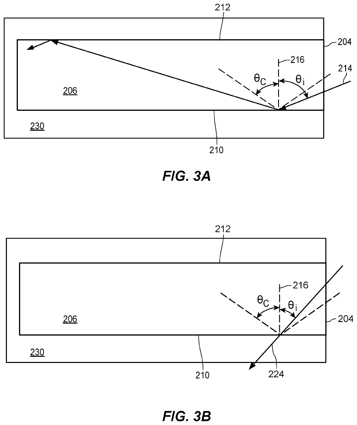
[0053]FIGS. 6A-6C depict various physical features that may be used to extract light from the otherwise internally-reflective radiation guiding medium 206. Of course, as will be familiar such physical features are generally very small, with a thickness of sub-millimeter scale and lateral dimensions at the millimeter or sub-millimeter scale. Thus, the features of FIGS. 6A-6C are not to scale but, rather, are depicted out of scale in order to be easily described. FIG. 6A depicts an embodiment 500 in which an excitation source 202 emits excitation energy 504 into a radiation guiding medium 206 through a perimeter surface 204. An excitation energy extraction pattern 508 on the first planar surface 210 of the planar radiation guiding medium 206 reflects the excitation energy 504 at an angle not guided by the radiation guiding medium 206. Reflected excitation energy 512 incident on the opposing planar surface 212 at angles less than the critical angle 214, as illustrated in FIG. 3, of the...
embodiment 520
[0057]FIG. 6C shows yet another alternative embodiment 520 in which scattering elements 548 in the volume of the planar radiation guiding medium 206 facilitate the extraction of excitation energy 512 from the planar radiation guiding medium 206. The excitation energy source 202 injects excitation energy 504 into the planar radiation guiding medium 206 through the perimeter surface 204. The scattering elements 548 suppress total internal reflection of the excitation energy 504 in the planar radiation guiding medium 206 resulting in diffuse output of reflected excitation energy 512. The scattered excitation energy 514 passes through the opposing planar surface 212 of the planar radiation guiding medium 206 into at least one area or region with a fluorophore or analyte.
[0058]With careful design of the extraction pattern 408, v-grooves 428, or scatterers 448 the excitation energy injected into a perimeter surface 204 by an excitation energy source 202 is able to be uniformly distributed...
PUM
| Property | Measurement | Unit |
|---|---|---|
| wavelength | aaaaa | aaaaa |
| distances | aaaaa | aaaaa |
| wavelength band | aaaaa | aaaaa |
Abstract
Description
Claims
Application Information