Modular vacuum insulated piping

a vacuum insulation and module technology, applied in the field of insulation systems, can solve the problems of high manufacturing cost of field built vacuum insulation piping systems, high cost of field work associated, and high production cost of vacuum required for conventional vacuum insulation systems for double walled piping systems, so as to facilitate the introduction of condensable gas and facilitate the pressurization and depressurization of insulation space.

Active Publication Date: 2021-06-29
PRAXAIR TECH INC
View PDF29 Cites 2 Cited by
  • Summary
  • Abstract
  • Description
  • Claims
  • Application Information

AI Technical Summary

Problems solved by technology

The vacuum required for conventional vacuum insulation systems for double walled piping systems is expensive to produce, requiring long pump out times at elevated temperatures when assembling the vacuum insulated piping system in the field.
This results in a high manufacturing cost for such field built vacuum insulated piping systems.
During construction of a cryogenic air separation plant, the costs associated with the field work associated with a vacuum insulated piping system or arrangement, namely steps (c) through (f) above, can often run near to or in excess of 50% of the total installed cost of the vacuum insulated piping system.
The field-based vacuum pull-down step alone is expensive and very time consuming.
In many instances of installing a vacuum insulation piping system for a cryogenic air separation plant, the field vacuum work can take between 2 to 7 days depending on the overall length and geometries of the vacuum insulated piping system or arrangement which translates to higher installation costs.
As a result, the vacuum levels for vacuum insulation piping systems where the vacuum is obtained in the field are somewhat inconsistent.

Method used


Image

  • Modular vacuum insulated piping
  • Modular vacuum insulated piping
  • Modular vacuum insulated piping

Examples


Embodiment Construction

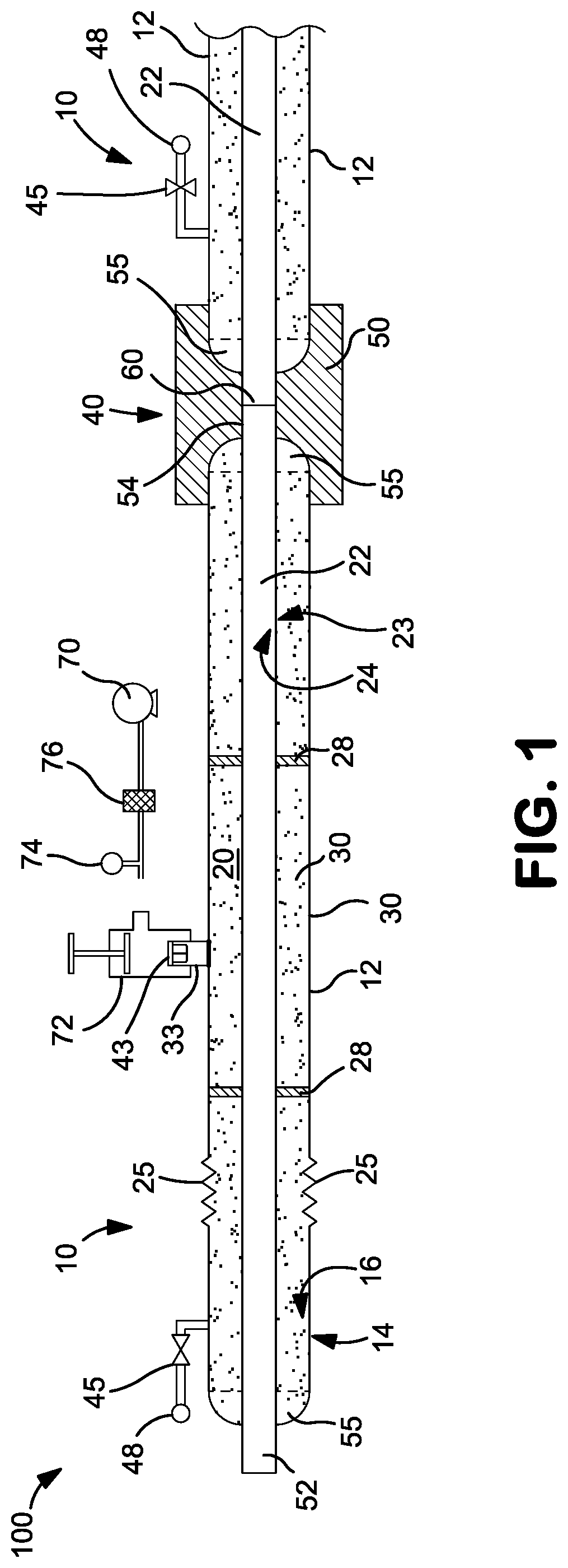
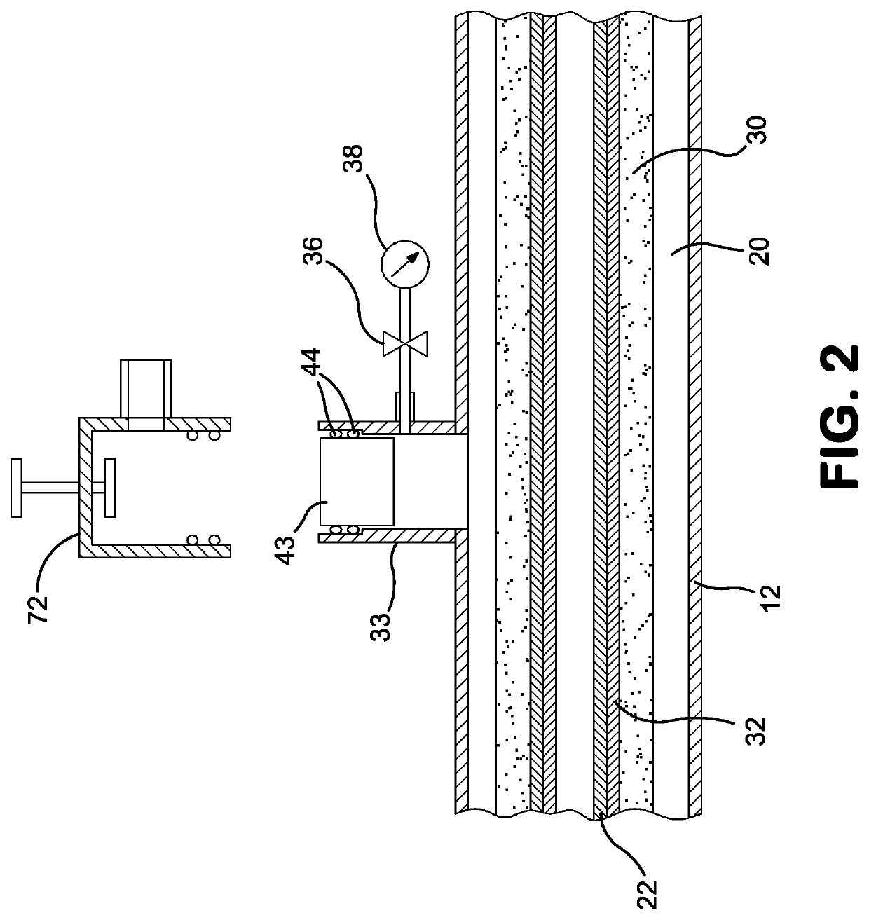
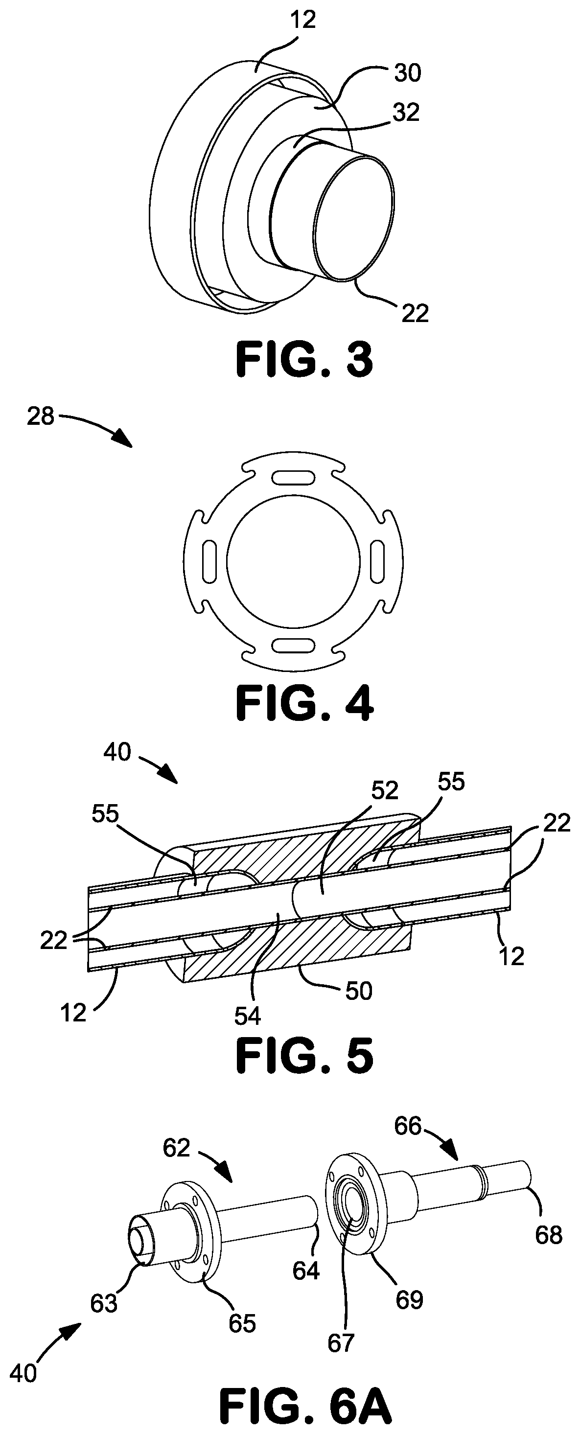
[0018]The presently claimed system and methods address the above-identified needs by fabricating individual double walled pipe sections with insulation, preferably aerogel based insulation, and designed to operate a vacuum level of between about 1 micron Hg and 300 micron Hg. The individual modular pipe sections are subsequently transported to the construction site where an aerogel-based vacuum insulated piping system is assembled by coupling a plurality of the pre-fabricated vacuum insulated pipe sections.

[0019]This pre-fabricated modular pipe section approach ensures the quality of each pipe section is uniform and consistent, including the construction of each pipe section as well as the vacuum system within each pipe section. Since the vacuum pull down of each pipe section occurs in the shop fabrication facility, the amount of time spent in the field installing or assembling the vacuum insulated piping system as well as the associated field installation costs and risks are minimi...


PUM


Abstract

A modular, aerogel-based vacuum insulated pipe section comprising an outer conduit; an inner conduit concentrically disposed within the outer conduit with aerogel insulation and a condensable gas being disposed in the insulation space between the concentric conduits. As a stand-alone pipe section, the insulation space is at a pressure within the range of from about 100 microns Hg to about 1000 microns Hg. However, in operation, when a cryogenic fluid is traversing the inner conduit, the condensable gas condenses and the pressure within the insulation space is further reduced to range of from about 1 microns Hg to about 5 microns Hg. The vacuum insulated pipe section further includes a coupling arrangement disposed on a first end of the inner conduit and a second end of the inner conduit, the coupling arrangement configured to engage or mate with a corresponding end of another modular vacuum insulated pipe section.

Description

CROSS REFERENCE TO RELATED APPLICATIONS[0001]The present application claims the benefit of and priority to U.S. provisional patent application Ser. No. 62 / 753,244 filed on Oct. 31, 2018, the disclosures of which are incorporated by reference herein.TECHNICAL FIELD[0002]The present invention relates generally to insulation systems intended for use at cryogenic temperatures and more particularly, to vacuum insulated pipe sections and assembled vacuum insulated piping systems or arrangements, preferably with aerogel based insulation.BACKGROUND[0003]Conventional cryogenic vacuum insulation systems for double walled piping systems require a vacuum, typically less than 1 micron Hg at 0° C. The purpose of the vacuum is to reduce gas conduction / convection so as to maintain the fluids contained in concentric conduits or other double walled piping systems at cryogenic temperatures, typically 170 Kelvin or below. The vacuum required for conventional vacuum insulation systems for double walled ...

Claims


Application Information

Patent Timeline
Patent Type & Authority Patents(United States)
IPC IPC(8): F16L59/065F16L59/02F16L53/32
CPCF16L59/065F16L53/32F16L59/026F16L59/028F16L59/141F16L59/143F16L59/184F16L59/08F16L59/06F16L59/12
Inventor VAZE, ADITYAPOTRATZ, SETH A.
Owner PRAXAIR TECH INC
Why Eureka
Try Eureka