
Light-to-frequency converter arrangement and method for light-to-frequency conversion

a technology of light-to-frequency converter and arrangement, which is applied in the direction of code conversion, optical radiation measurement, instruments, etc., can solve the problems of small loss of light-to-frequency converter, large error, and failure to accurately estimate incident light, etc., to achieve accurate measurement, solve and measure accurately residual signal, and achieve the effect of avoiding significant loss of accuracy

Active Publication Date: 2021-06-29
AMS INT
View PDF5 Cites 0 Cited by
  • Summary
  • Abstract
  • Description
  • Claims
  • Application Information

AI Technical Summary

Benefits of technology

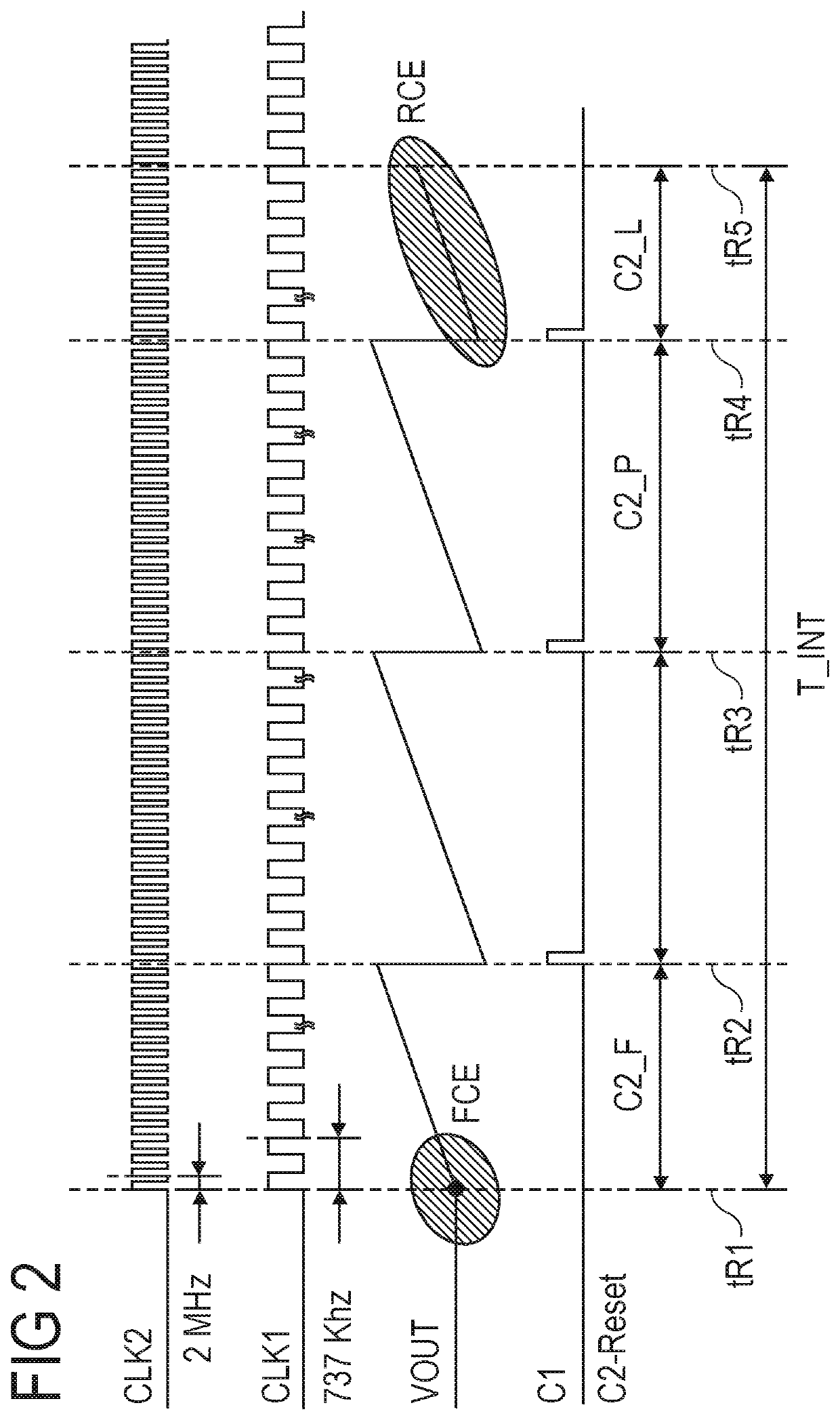
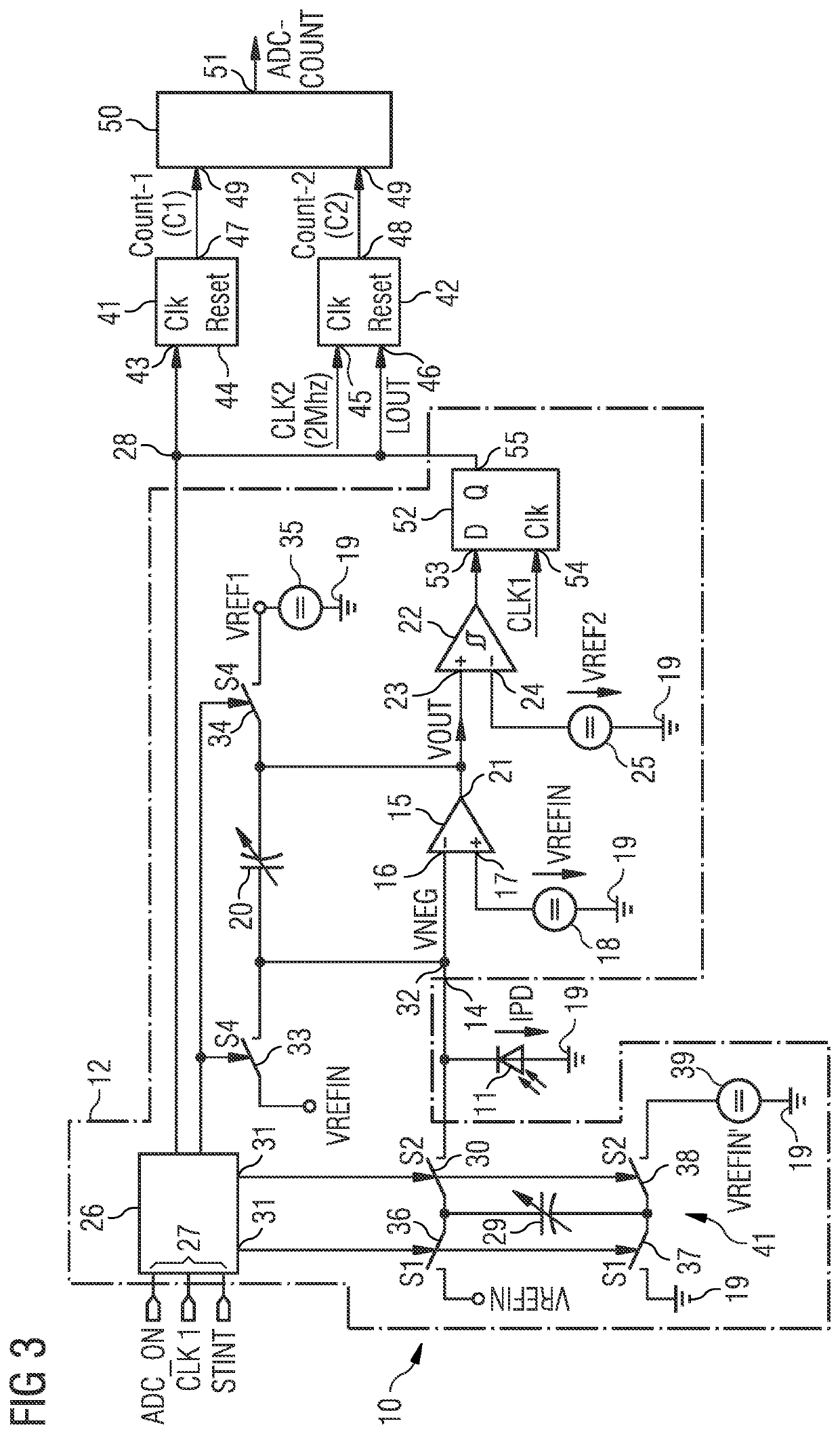
[0023]The improved concept is based on the idea that several sources of error in our light to frequency conversion can be accounted for by calculating error estimates from fractional counts. The proposed method and architecture can resolve and measure accurately the residual signal of the last integration cycle of the analog-to-digital converter. This way an accurate measurement can be achieved even from low counts of the converter. The digital output signal can be scaled with a multiplier without significant loss of accuracy for a wide range.

Problems solved by technology

However, in low light conditions light-to-frequency conversion embedded in optical sensor arrangement often fails to give an accurate estimate of the incident light.
Typically, only few counts are detected and losing a few counts can manifest in a larger error than under bright light conditions.

Method used


Image

  • Light-to-frequency converter arrangement and method for light-to-frequency conversion
  • Light-to-frequency converter arrangement and method for light-to-frequency conversion
  • Light-to-frequency converter arrangement and method for light-to-frequency conversion

Examples


Embodiment Construction

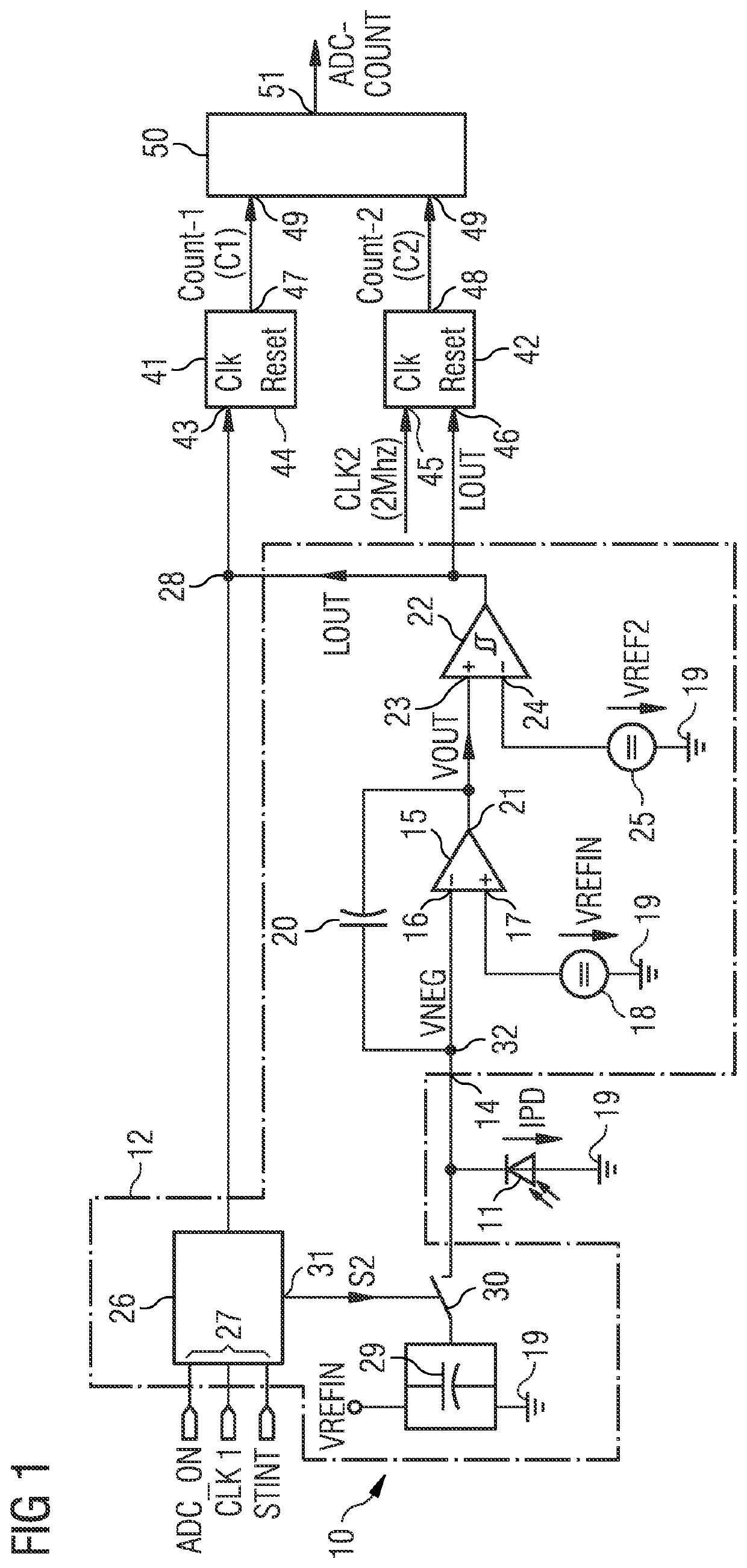
lass="d_n">[0031]FIG. 1 shows an exemplary embodiment of an optical sensor arrangement 10. The optical sensor arrangement 10 comprises a photodiode 11 and an analog-to-digital converter arrangement 12, abbreviated as converter hereinafter. Furthermore, the optical sensor arrangement 10 comprises a signal processing unit 40. The converter 12 and the signal processing unit 40 are combined into a light-to-frequency converter which may be designed as an integrated circuit.

[0032]Typically, the photodiode 11 is connected to the integrated circuit as an external component but may just as well be part of the integrated circuit in some embodiments. The light-to-frequency converter and photodiode can be considered an optical sensor arrangement hereinafter. In one or more embodiments the optical sensor arrangement is used an ambient light sensor. Similar circuits are described in EP 2863192 A1 and EP 2787331 A1 which are included by reference.

[0033]The photodiode 11 is connected to an input 14...


PUM

PropertyMeasurementUnit
frequencyaaaaaaaaaa
frequencyaaaaaaaaaa
integration time TINTaaaaaaaaaa

Abstract

A method for light-to-frequency conversion comprises generating a photocurrent by means of a photodiode and converting the photocurrent into a digital comparator output signal in a charge balancing operation depending on a first clock signal. From the digital comparator output signal an asynchronous count is determined and comprises an integer number of counts depending on the first clock signal. From the digital comparator output signal a fractional time count is determined and depends on a second clock signal. Finally, from the asynchronous count and from the fractional time count a digital output signal is calculated which is indicative of the photocurrent generated by the photodiode. The method may be carried out by an exemplary light-to-frequency converter equipped with a photodiode.

Description

[0001]This invention relates to a light-to-frequency converter arrangement and to a method for Light-to-frequency conversion.BACKGROUND OF THE INVENTION[0002]Optical sensors such as ambient light sensors find increasing application in mobile devices such as Smartphones, tablets or in various electronic equipment related to television or room lighting. Under normal light conditions the optical sensors and their dedicated signal processing circuits have reached a state of development that allows for an accurate measure of lighting conditions or even colors of lighting under changing lighting. However, in low light conditions light-to-frequency conversion embedded in optical sensor arrangement often fails to give an accurate estimate of the incident light. Typically, only few counts are detected and losing a few counts can manifest in a larger error than under bright light conditions.[0003]It is to be understood that any feature described hereinafter in relation to any one embodiment m...

Claims


Application Information

Patent Timeline
Patent Type & Authority Patents(United States)
IPC IPC(8): G01J1/44H03M1/60
CPCG01J1/44H03M1/60G01J2001/446H03M1/145H04N25/772
Inventor RANGANATHAN, ROHITADUSUMALLI, RAVI KUMAR
Owner AMS INT
Learn More