Vehicle seat structure
a seat structure and vehicle technology, applied in the field of vehicle seat structure, can solve the problems that the actual experience of seated occupants cannot be improved, and achieve the effect of reducing rigidity differences and improving traveling comfort of seated occupants
- Summary
- Abstract
- Description
- Claims
- Application Information
AI Technical Summary
Benefits of technology
Problems solved by technology
Method used
Image
Examples
first embodiment
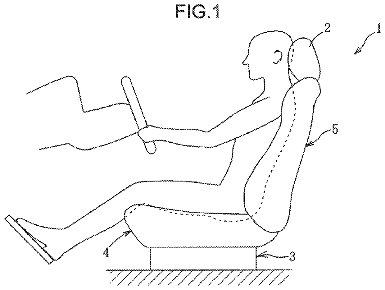
[0024]A first embodiment according to the present invention is described with reference to FIGS. 1 to 7.
[0025]As illustrated in FIG. 1, a vehicle seat 1 according to the first embodiment includes, as main constituent elements, a head rest for receiving the head of a seated occupant, a leg mechanism 3 for fixing the seat 1 to a passenger compartment floor, a seat cushion 4 for supporting a part (buttock) corresponding to the ischial bone of the seated occupant, and a seat back 5 for supporting a part (back) corresponding to the spine (backbone) of the seated occupant.
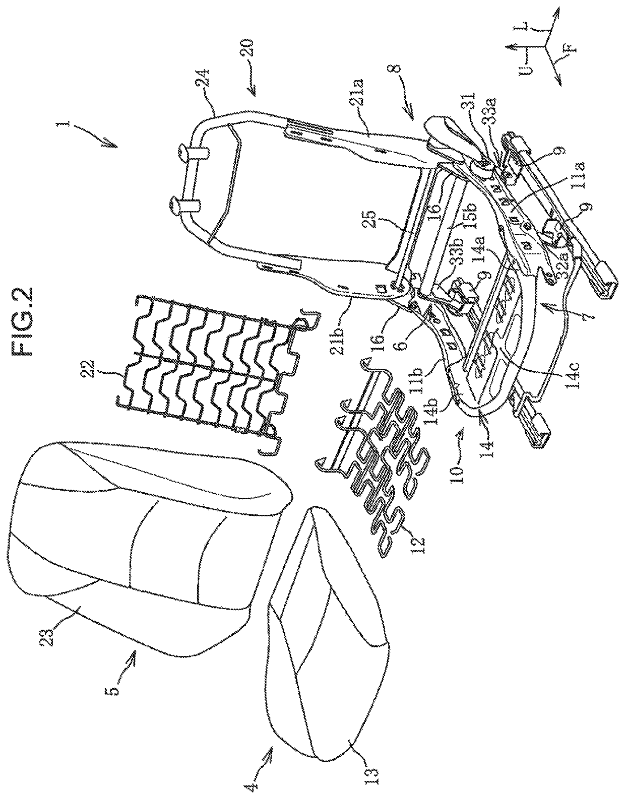
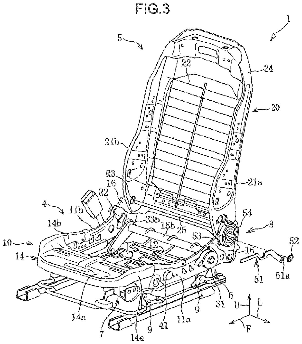
[0026]The seat 1 includes, as a posture changing mechanism for adjusting a seated posture of the occupant, a lifter mechanism 6 capable of changing a height position of the seat cushion 4, a tilt mechanism 7 capable of changing a height position of a front end of the seat cushion 4, and a reclining mechanism 8 capable of changing a tilt angle of the seat back 5.
[0027]In the following description, “front”, “rear”, “left”,...
second embodiment
[0100]Next, a vehicle seat 1A according to a second embodiment of the present invention is described with reference to FIGS. 8 to 10. In FIGS. 8 to 10, members similar to those in the first embodiment are indicated with the same reference numbers, and detailed description thereof is omitted.
[0101]Whereas, in the first embodiment, manually operated posture changing mechanisms (6 to 8) are employed, in the second embodiment, electrically operated posture changing mechanisms (6A to 8A) to be driven by electric motors M1 to M3 are employed.
[0102]As illustrated in FIGS. 8 to 10, the lifter mechanism 6A includes an operation portion 31A to be operated by an occupant, the motor M1 to be driven in response to an operation of the operation portion 31A, a pinion 31a, and a 4-link mechanism. The motor M1 is disposed on an outer surface (left surface) of the left side frame 11a, and is able to drive and rotate the pinion 31a.
[0103]The tilt mechanism 7A includes an operation portion 41A to be o...
PUM
 Abstract
Description
Claims
Application Information
 - R&D Engineer
- R&D Manager
- IP Professional
- Industry Leading Data Capabilities
- Powerful AI technology
- Patent DNA Extraction
Browse by: Latest US Patents, China's latest patents, Technical Efficacy Thesaurus, Application Domain, Technology Topic, Popular Technical Reports.
© 2024 PatSnap. All rights reserved.Legal|Privacy policy|Modern Slavery Act Transparency Statement|Sitemap|About US| Contact US: help@patsnap.com


