Tread pattern of bicycle tire

A tread pattern and bicycle technology, applied in the field of tread pattern, can solve the problems such as the negative impact of tire weight reduction, the inability to fully grip the road, and insufficient cornering grip, so as to improve cornering support and force return Elasticity, reducing rigidity difference, and reducing rigidity

Pending Publication Date: 2019-03-01
CHENG SHIN RUBBER (XIAMEN) IND LTD
View PDF0 Cites 0 Cited by
  • Summary
  • Abstract
  • Description
  • Claims
  • Application Information

AI Technical Summary

Problems solved by technology

[0006] Firstly, the addition of the side pattern blocks 30' can reduce the difference in rigidity when going straight and turning to a certain extent, but the conventionally designed side pattern blocks 30' are all regular polygonal blocks, and the resulting edge components are limited to polygonal contact surfaces. The cornering grip is still insufficient, and the effect of easing the instant drop feeling when going straight and cornering is not obvious;
[0007] Secondly, in order to provide sufficient cornering support capacity, the conventionally designed shoulder block 20' is usually a large-volume block and designed with an inclined outer sidewall 21', and the outer sidewall 21' is inclined at a large angle along the outer side of the shoulder block 20' Extending, by increasing the volume of the shoulder block 20' to improve the support of the shoulder when cornering, but the substantial increase in rigidity makes the shoulder block 20' hard to deform under force, and cannot fully grasp the road surface, but it is easy to cause cornering Insufficient ground performance may also lead to too fast rebound when cornering and grounding, making the tires feel unstable when turning back to straight;
[0008] Finally, the addition of side tread blocks 30' and large-volume shoulder tread blocks 20' has a negative impact on tire weight reduction, and there is still room for improvement

Method used


Image

  • Tread pattern of bicycle tire
  • Tread pattern of bicycle tire
  • Tread pattern of bicycle tire

Examples


Embodiment

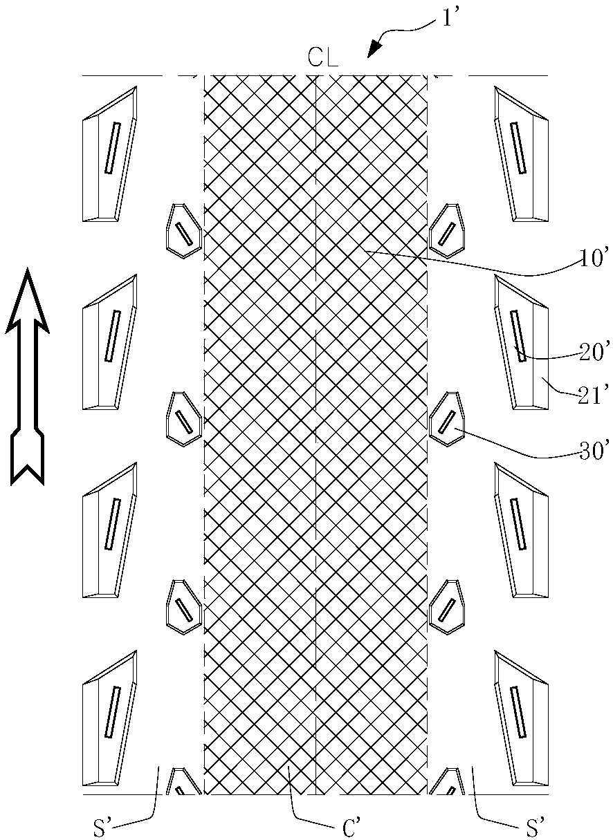
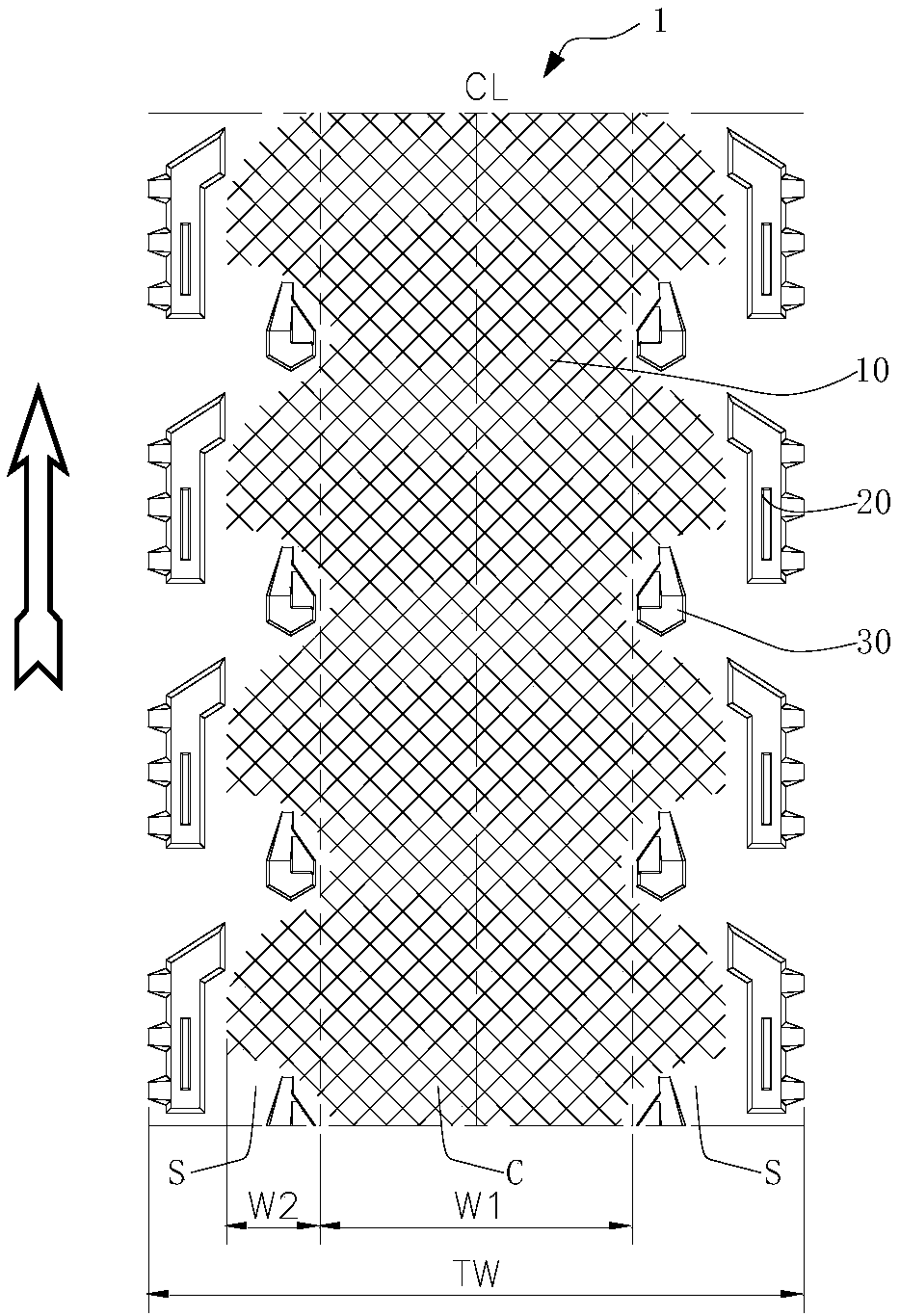
[0040] Such as Figure 2 to Figure 10 As shown, the present invention discloses a bicycle tire tread pattern. exist figure 2 In , the vertical direction is set as the tire circumferential direction, the lateral direction is set as the tire axial direction, CL represents the centerline of the tread, and the arrow points to the tire rolling direction. The front and rear of the present invention are defined according to the rolling direction of the tire, and the first ground contact end is defined as the front end, and the rear ground contact end is defined as the rear end.

[0041] Such as figure 2 As shown, the tread 1 includes a central region C and side regions S located on both sides of the central region C, the central region C ( figure 2 The region defined between the two dotted lines) is symmetrical to the tread centerline CL, and its expanded width W1 is 50%-65% of the total tread expanded width TW. Fine patterns 10 are arranged in the central area C, and irregula...


PUM


Abstract

The invention discloses a tread pattern of a bicycle tire. Fine patterns extend from the central region to side regions, the axial outer sides of the fine patterns are in the shapes of waves which extend in the circumferential direction of the tire, and side pattern blocks and tire shoulder pattern blocks are respectively penetrated in wave bottoms and wave heads. The side pattern blocks of the tread pattern of the bicycle tire are d-shaped composite blocks defined by three polygonal three-dimensional faces with different heights, angles and shapes to reduce the rigidity difference, improve the turning stability and ground griping performance and rationalize the weights of the side pattern blocks. The tire shoulder pattern blocks of the tread pattern comprise bent front parts and long strip-shaped rear parts, a plurality of outer-layer clamping jaws are overlapped on the inner-layer walls of the rear parts, parameters of the inner-layer walls and the outer-layer clamping jaws are optimized to improve the bending support and force resilience so as to improve the turning stability of the tire and reduce the sense of instability. The tire shoulder pattern blocks are cut into two independent pattern blocks to limit the cutting distance and position, so as to keep performance advantages of the tire shoulder pattern blocks and appropriately reduce the rigidity, and further increase the force resilience and edge composition, and enhance ground griping performances.

Description

technical field [0001] The invention relates to the field of bicycle tires, in particular to a tread pattern of a bicycle tire. Background technique [0002] Lightweight is the technical development trend of the bicycle industry in recent years, especially in the field of high-end bicycles, which has high requirements for the lightweight of the whole vehicle and its accessories, which not only affects the riding performance, but also reflects the high added value. [0003] In order to reduce the weight, the current lightweight bicycle tires are designed with thinner and shallower patterns on the tread surface, such as figure 1 Shown is the pattern of the tire tread on the existing common light-weight bicycles. Usually, fine patterns 10' are arranged in the central area C' of the tread 1' to reduce the weight of the tire and seek lower rolling resistance and better In order to ensure the basic cornering grip and safety requirements of various road conditions, shoulder blocks...

Claims


Application Information

Patent Timeline
Patent Type & Authority Applications(China)
IPC IPC(8): B60C11/03B60C11/11
CPCB60C11/03B60C11/11B60C2011/0386B60C2011/039B60C2200/12
Inventor 陈秀雄
Owner CHENG SHIN RUBBER (XIAMEN) IND LTD
Why Eureka
Try Eureka