Analyzing device and flow path plate

a technology of flow path plate and analyzer, which is applied in the direction of measurement device, scientific instruments, instruments, etc., can solve the problem of taking a long time to replace the flow cell, and achieve the effect of improving the accuracy and reliability of the flow cell

Active Publication Date: 2021-07-13
ALPS ALPINE CO LTD
View PDF21 Cites 0 Cited by
  • Summary
  • Abstract
  • Description
  • Claims
  • Application Information

AI Technical Summary

Benefits of technology

[0084]The analyzing device according to one aspect of the present invention can easily and accurately adjust the position of the optical axis of the light illuminated by the optical component.

Problems solved by technology

In addition, when it became difficult to reuse the flow cell due to the inability to completely remove dirt in the flow cell even after cleaning the flow cell, the flow cell was replaced.
When replacing the flow cell, it took a long time to replace the flow cell because of the need to precisely align the optical components in the main body of the analyzing device with the new flow cell.

Method used


Image

  • Analyzing device and flow path plate
  • Analyzing device and flow path plate
  • Analyzing device and flow path plate

Examples


Embodiment Construction

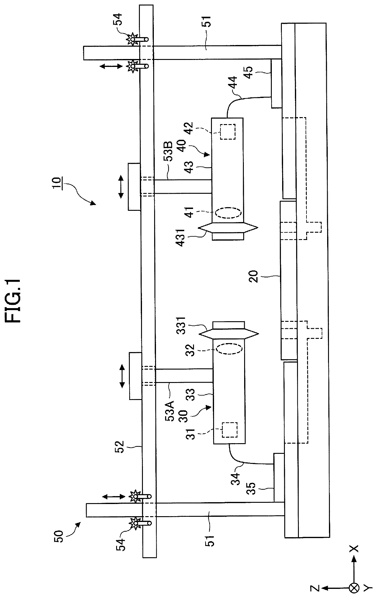
[0024]Hereinafter, embodiments of the present invention will be described in detail. For ease of comprehension, the scale of each member in the drawings may differ from the actual scale. In the following description, one of the height directions of the analyzing device is referred to as high, up, or upward, and the other of the height direction of the analyzing device is referred to as low, down, or downward. In this specification, the three-dimensional orthogonal coordinate system using three axes (X-axis direction, Y-axis direction, and Z-axis direction) are used. The width direction of the analyzing device is set to the X direction, the depth direction is set to the Y direction, and the height direction is set to the Z direction.

[0025]An analyzing device according to the embodiment will be described. FIG. 1 is a schematic diagram illustrating an analyzing device with a flow path chip according to an embodiment. As illustrated in FIG. 1, the analyzing device 10 according to the em...


PUM

PropertyMeasurementUnit
permeabilityaaaaaaaaaa
optical axisaaaaaaaaaa
areaaaaaaaaaaa

Abstract

An analyzing device includes a flow path plate having a flow path, through which a liquid flows, shaped like a rectangle, and having a light permeability, a light emitting unit having a light emitting lens and emitting light, and a light receiving unit including a light receiving lens and receiving the light, the analyzing device analyzing the liquid flowing inside the flow path plate, wherein the flow path plate has a pair of cutouts formed at an end face so as to face each other through a part of the flow path, wherein the pair of cutouts includes a first cutout in which the light emitting unit is disposed and a second cutout in which the light receiving unit is disposed.

Description

CROSS-REFERENCE TO RELATED APPLICATION[0001]The present application is a continuation application of International Application No. PCT / JP2018 / 025488, filed Jul. 5, 2018, which claims priority to Japanese Patent Application No. 2017-136157, filed Jul. 12, 2017. The contents of these applications are incorporated herein by reference in their entirety.BACKGROUND OF THE INVENTION1. Field of the Invention[0002]The present invention relates to an analyzing device and a flow path plate.2. Description of the Related Art[0003]There is an analyzing device that uses a flow path plate (also called a flow path tip) to analyze trace substances, such as proteins and nucleic acids, contained in body fluids (blood or liquids secreted or excreted inside or outside the body (including sweat and saliva) and chemicals contained in effluent discharged from factories.[0004]The flow path plate requires a small amount of sample and reagent for analysis and can be analyzed accurately and in a short time. The...

Claims


Application Information

Patent Timeline
Patent Type & Authority Patents(United States)
IPC IPC(8): G01N21/59G01N30/74G01N30/60G01N21/85
CPCG01N21/59G01N21/85G01N30/60G01N30/74G01N2201/068G01N21/05G01N21/13G01N2021/0378G01N30/6095
Inventor ITO, JUNKO
Owner ALPS ALPINE CO LTD
Why Eureka
Try Eureka