Illumination System for an Ophthalmic Surgical Microscope, Ophthalmic Surgical Microscope, and Method for Operating an Illumination System for an Ophthalmic Surgical Microscope

Active Publication Date: 2011-10-27
LEICA MICROSYSTEMS (SCHWEIZ) AG
View PDF3 Cites 5 Cited by
  • Summary
  • Abstract
  • Description
  • Claims
  • Application Information

AI Technical Summary

Benefits of technology

[0013]Another advantage of the present invention is that it reduces the risk of damage to the patient's eye during illumination thereof as compared to known methods. In particular, when illuminating a patient's eye which is hyperopic and thus relatively short and, as experience shows, inherently provides a relatively good red reflex, it may be possible by suitable adjustment of the optical element to keep the illuminated retinal area (hereinafter also referred to as “illuminated area”) away from the particularly light-sensitive macula without significantly reducing the quality of the red reflex. This may be achieved via a relationship empirically established, for example prior to surgery, between the measured parameter and the control parameter.
[0014]Preferably, the measuring device includes a measuring unit for measuring the parameter of the patient's eye in situ. Measuring the parameter in situ; i.e, during surgery, allows the illumination to be flexibly adapted to variations in the characteristics of the patient's eye during surgery. For example, the red reflex may change during cataract surgery upon removal of the eye lens from its capsule. If, in this case, an optical parameter reflecting this change is measured in situ, then the red reflex illumination can be adapted to the changed conditions.
[0015]Preferably, the measuring unit is a refractometer. However, the present invention is not limited to such a measuring unit. For example, a coherence interferometer, a skiascope or a keratometer may also be used as the measuring

Problems solved by technology

However, this approach

Method used


Image

  • Illumination System for an Ophthalmic Surgical Microscope, Ophthalmic Surgical Microscope, and Method for Operating an Illumination System for an Ophthalmic Surgical Microscope
  • Illumination System for an Ophthalmic Surgical Microscope, Ophthalmic Surgical Microscope, and Method for Operating an Illumination System for an Ophthalmic Surgical Microscope
  • Illumination System for an Ophthalmic Surgical Microscope, Ophthalmic Surgical Microscope, and Method for Operating an Illumination System for an Ophthalmic Surgical Microscope

Examples


Embodiment Construction

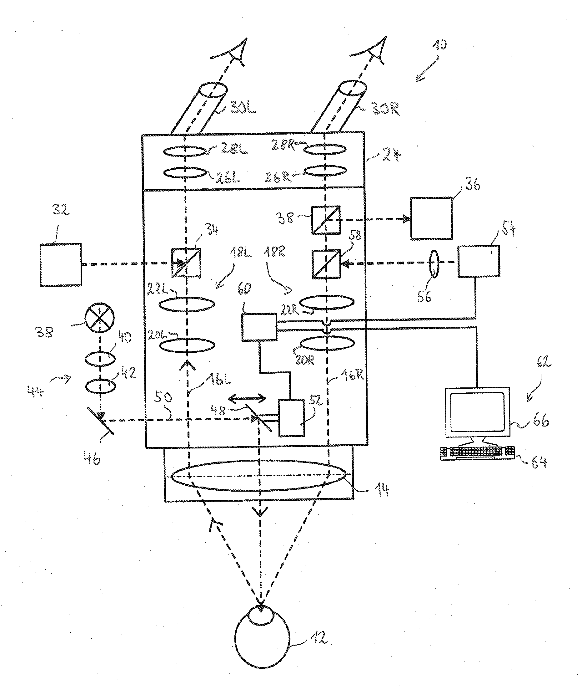
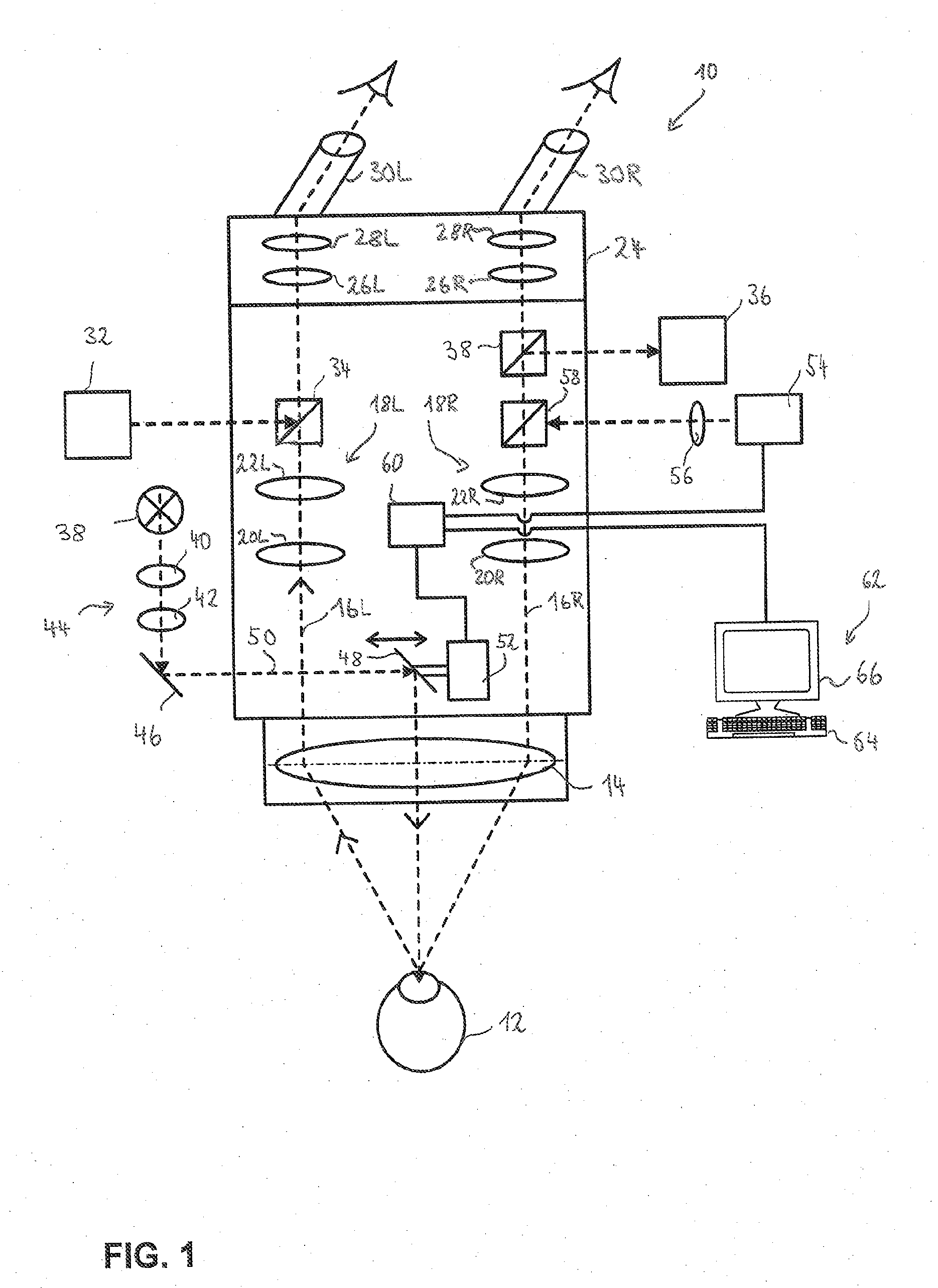
[0024]FIG. 1 shows a stereoscopic ophthalmic microscope 10 which, in the present exemplary embodiment, is used to perform cataract surgery on a patient's eye 12.

[0025]Stereomicroscope 10 has a common objective 14 for a left and a right observation beam path 16L, respectively 16R. Observation beam paths 16L and 16R each contain zoom optics 18L, respectively 18R, which are schematically indicated in FIG. 1 by two lenses 20L, 22L, respectively 20R, 22R.

[0026]Observation beam paths 16L and 16R extend into a tube 24, which contains tube lenses 26L and 28L associated with left observation beam path 16L, as well as tube lenses 26R and 28L [sic. 28R] associated with right observation beam path 16R. Moreover, tube 24 has eyepieces 30L and 30R attached thereto which are associated with left observation beam path 16L, respectively right observation beam path 16R.

[0027]Stereomicroscope 10, as shown in FIG. 1, further has an image overlay projection device 32, which generates and projects data i...


PUM


Abstract

Disclosed is an illumination system for an ophthalmic surgical microscope (10), including a light source (32) for emitting light along an illumination beam path (50) directed toward an eye (12) of a patient, and a measuring device (54, 62) for measuring a parameter of the patient's eye (12). The illumination system further includes an adjustable optical element (48) which allows the orientation of the illumination beam path (50) to be adjusted relative to an observation beam path (16L) of the surgical microscope (10) so as to obtain a red reflex, and a control device (60) which determines a red-reflex-optimized control parameter based on the measured parameter of the patient's eye (12) and adjusts the optical element (48) according to the red-reflex-optimized control parameter.

Description

CROSS-REFERENCE TO RELATED APPLICATIONS[0001]This Application claims priority to German Patent Application No. DE 10 2010 016 623.5 filed on Apr. 23, 2010, that is incorporated herein by reference in its entirety.FIELD OF THE INVENTION[0002]The present invention relates to an illumination system for an ophthalmic surgical microscope, including a light source for emitting light along an illumination beam path directed toward an eye of a patient, and a measuring device for measuring a parameter of the patient's eye. The present invention also relates to an ophthalmic surgical microscope, and to a method for operating an illumination system for an ophthalmic surgical microscope.BACKGROUND OF THE INVENTION[0003]In eye surgery, the illumination in an ophthalmic surgical microscope must often meet special requirements. For example, in cataract surgery, illumination systems are used which illuminate the patient's eye in such a way that the illumination beam path extends substantially coaxi...

Claims


Application Information

Patent Timeline
IPC IPC(8): A61B3/13A61B3/103
CPCA61B3/132A61B19/5202G02B21/06G02B21/0012A61B19/5223A61B90/30A61B90/20
Inventor SANDER, ULRICH
Owner LEICA MICROSYSTEMS (SCHWEIZ) AG
Why Eureka
Try Eureka