Eureka AIR delivers breakthrough ideas for toughest innovation challenges, trusted by R&D personnel around the world.

Orthodontic bracket apparatus and method for treating a malocclusion

a technology for orthodontic brackets and brackets, which is applied in the direction of brackets, arch wires, etc., can solve the problems of difficult placement and secure, clinically desirable deployment, placement or installation of orthodontic brackets, especially on the upper and lower cuspids of patients, and often proved problematic. to achieve the effect of facilitating the orthodontic treatment regimen

Active Publication Date: 2021-07-20
PREMIER ORTHODONTIC DESIGNS LLLP
View PDF26 Cites 0 Cited by
  • Summary
  • Abstract
  • Description
  • Claims
  • Application Information

AI Technical Summary

Benefits of technology

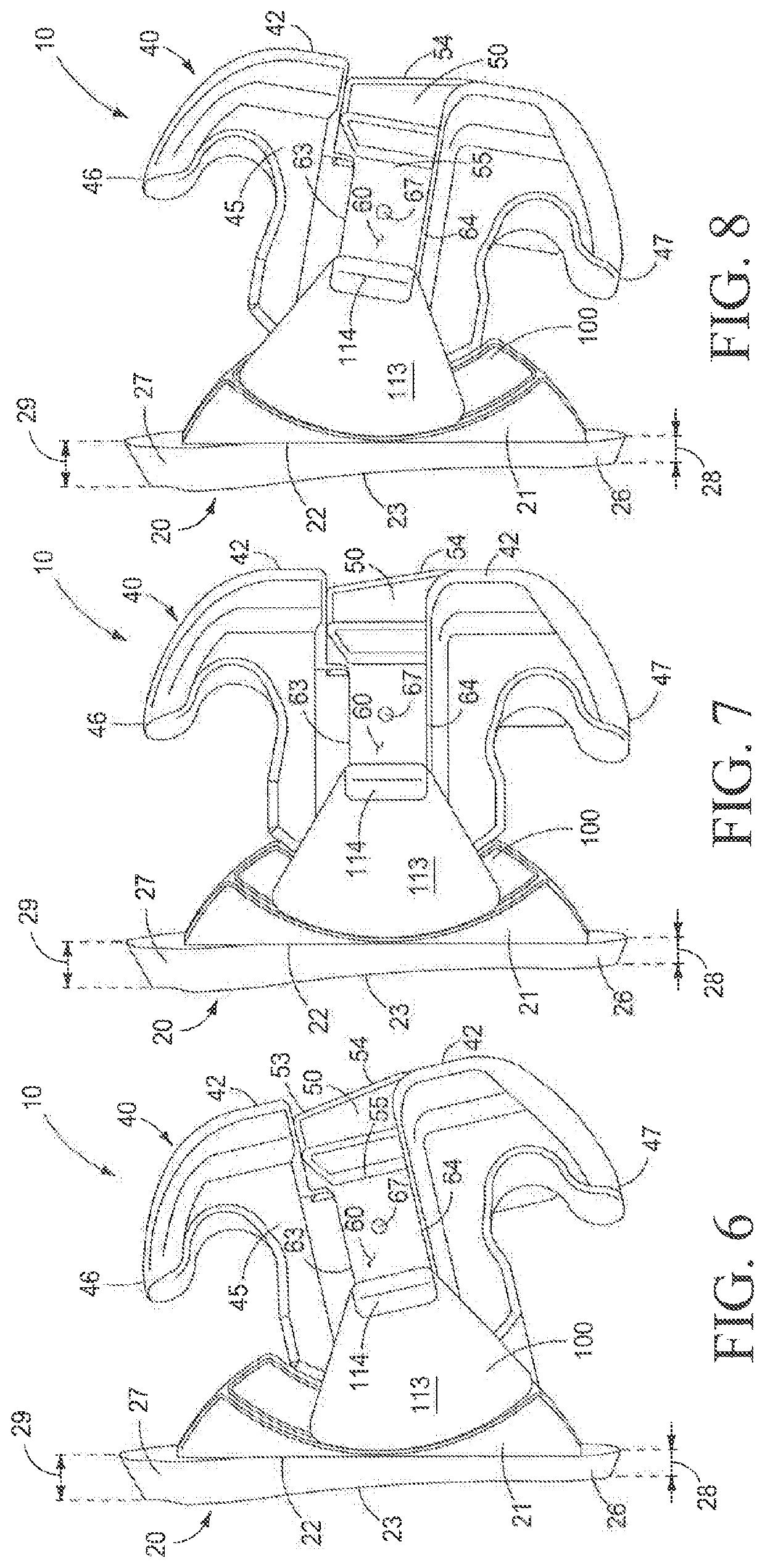
[0010]A further aspect of the present invention is an orthodontic bracket apparatus further comprising a medial passageway defined in the bracket body communicating from the base wall of the archwire slot to an opposing posterior surface of the bracket body, and a transversely extending through hole defined in the bracket body spacedly adjacent the posterior surface and perpendicular to the archwire slot, the transverse through hole intersecting the medial passageway and configured to releasably carry a retention pin therein; and wherein the bracket body insert has an elongated main body with the first end, a second end, a top, a bottom, an anterior facing surface, a posterior facing surface and an engagement member configured to be axially received within the medial passageway defined by the bracket body, the engagement member extending generally perpendicularly from the posterior facing surface medially between the first end and the second end, the engagement member further has a distal end spaced apart from the main body and defines an elongated hole communicating between the top and the bottom, and between the distal end and the main body, and when the engagement member is engaged within the medial passageway defined by the bracket body, the elongated hole is aligned with the transverse through hole defined in the bracket body, and the engagement member carries friction ridges thereon to frictionally communicate with peripheral surfaces of the medial passageway to eliminate any “movement” therebetween; and the elongated hole defined in the engagement member, in cooperation with the retention pin extending therethrough allows limited axial movement of the bracket body insert relative to the bracket body so as to allow the bracket body to be rotatably moved relative to the respective bracket base permitting the treating clinician to adjust the relative position of the respective bracket bodies relative to the respective bracket bases so as to facilitate the orthodontic treatment regimen of the patient.
[0011]A further aspect of the present invention is an orthodontic bracket apparatus wherein the bracket body insert is operable to cooperate with the respective bracket bodies, and which further releasably secures the respective bracket bodies in a predetermined orientation relative to the bracket base and the patient's tooth during the orthodontic treatment regimen, and wherein the respective bracket bodies each have an anterior facing surface which defines an arch wire slot, and an opposite posterior facing surface which moveably cooperates with the bracket base, and wherein the bracket body insert is conformably dimensioned to be received in the arch wire slot, and wherein a passageway extends through the respective bracket bodies from the arch wire slot to the posterior facing surface of the respective bracket bodies, and wherein the bracket body insert further comprises an elongated main body having a flange portion at an end portion of the elongated main body, and wherein the flange portion extends outwardly relative to the bracket body, and is further dimensioned to be received within a side recess defined in a side portion of the bracket base when the bracket body insert is engaged with both of the bracket body and the bracket base, and wherein the flange portion is configured so as to permit limited movement of the bracket body insert relative to the respective bracket body and arch wire slot, but prevents removal of the bracket body insert from the arch wire slot, and wherein the limited movement of the bracket body insert relative to the bracket body permits a clinician to adjust the relative position of the respective bracket bodies relative to the bracket base so as to facilitate the orthodontic treatment regimen of the patient.

Problems solved by technology

Consequently, some clinicians often found it difficult to place and secure individual arch wires within the arch wire slot, and further, it was oftentimes difficult for patients to maintain the cleanliness of their teeth because of the close spacial tolerances of the bracket bodies relative to the adjacent pad, and which supports the bracket body on the patient's tooth.
Still further, achieving a clinically desirable deployment, placement or installation of these orthodontic brackets, especially on the upper and lower cuspids of a patient, often proved problematic.
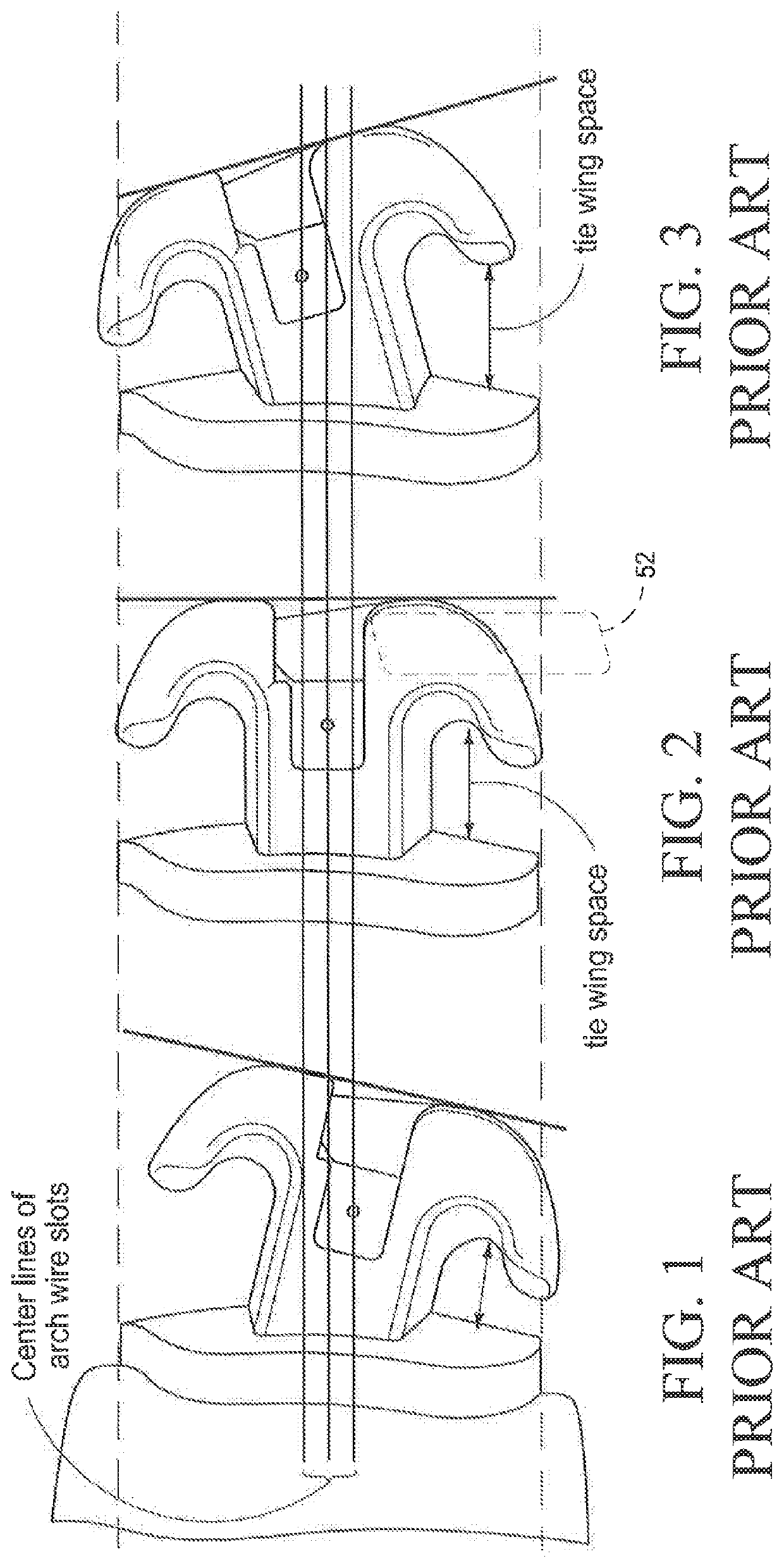
As can be imagined by studying FIGS. 1-3, the visual alignment of these prior art orthodontic brackets by a clinician on adjacent teeth of a patient, and in the same horizontal plane, by the alignment of the respective pads was virtually impossible to achieve because of the different angular orientations of each bracket body.
Additionally, the use of these prior art passive ligation orthodontic brackets often created other perceived difficulties for many clinicians inasmuch as the physical orientation of the bracket body often prevented or made it problematic for the clinician to appropriately orient the respective orthodontic brackets on adjacent teeth in order to achieve an ideal arch wire slot lineup which would facilitate the proper amount of torque being applied to the individual teeth undergoing correction.
However, because of the problems associated with the tie wing spacing, and which has often restricted the placement of C-chains, and elastics, on these appliances, and the problems associated with aligning the orthodontic bracket with adjoining orthodontic brackets to try and achieve level arch wire slot line-up, these orthodontic brackets have not been as widely embraced by clinicians as might have been expected.
In fact, the aforementioned shortcomings has been one of the major objections of many clinicians to utilizing passive ligation orthodontic brackets to achieve the kind of orthodontic treatment which is desired.
In view of the aforementioned perceived shortcomings, many clinicians have failed to adopt this type or style of orthodontic bracket in their clinical practice.
Consequently, the treatment times for many patients is often unduly long, and on many occasions, clinicians are not able to achieve the proper final tooth orientation which is desired for their patients.
While the aforementioned new orthodontic bracket as seen in U.S. Pat. No. 9,198,740, and the new arch wire as described in U.S. patent application Ser. No. 14 / 976,074 have operated with a great deal of success, some difficulties still remain for clinicians in establishing the proper orientation or placement of an orthodontic bracket on a patient's teeth, such as on the upper and lower cuspids.

Method used


Image

  • Orthodontic bracket apparatus and method for treating a malocclusion
  • Orthodontic bracket apparatus and method for treating a malocclusion
  • Orthodontic bracket apparatus and method for treating a malocclusion

Examples


Embodiment Construction

[0069]This disclosure of the invention is submitted in furtherance of the constitutional purposes of the U.S. Patent laws to “promote the progress of science and useful arts” (Article I, Section 8).

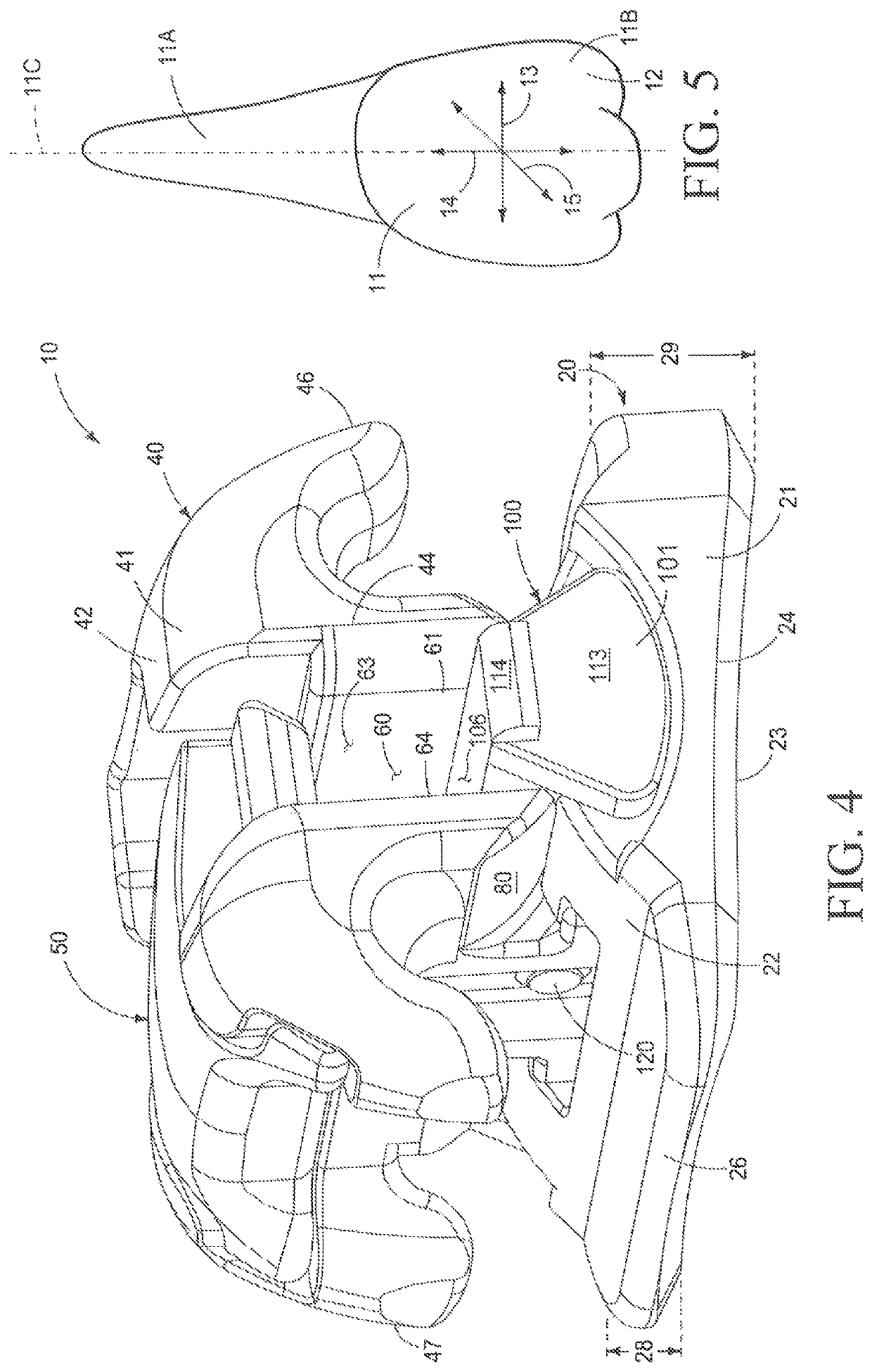
[0070]The first form of the present invention is generally indicated by the numeral 10 in FIG. 4 and following. For purposes of the present invention, it will be understood that the various forms of the invention, as described, hereinafter, will be used to implement a multiple-step orthodontic treatment method, regimen or plan, which is provided by a clinician to treat one or several orthodontic anomalies which a patient possesses. The orthodontic bracket 10 of the present invention is releasably affixed by means of a suitable adhesive or other means to a patient's tooth 11 (FIG. 5) and in particular to the anterior facing surface 12 thereof. The orthodontic bracket 10, in its various forms, will be discussed, hereinafter, and when used in combination with an arch wire 90, and other ortho...


PUM


Abstract

An orthodontic bracket apparatus and method for treating a malocclusion includes a bracket base having an angulated posterior facing surface and which is matingly and releasably positioned adjacent to an anterior facing surface of a patient's tooth; a multiplicity of bracket bodies releasably and adjustably engageable with the bracket base; and an arch wire simultaneously engageable within an arch wire slot defined in each of the bracket bodies to exert first, second and third order movements to the maloccluded tooth; and wherein the bracket base remains affixed to the patient's tooth throughout the multiple step orthodontic treatment regimen selected by the treating clinician.

Description

RELATED APPLICATIONS[0001]This utility patent application is a Continuation-In-Part (CIP) patent application of co-pending U.S. patent application Ser. No. 14 / 702,961 filed on May 4, 2015. The inventors of the instant invention are the same named inventors of earlier filed co-pending U.S. Ser. No. 14 / 702,961. The entire contents of aforementioned co-pending U.S. Ser. No. 14 / 702,961, and the teaching's thereof, are expressly incorporated herein by this reference.TECHNICAL FIELD[0002]The present invention relates to an orthodontic bracket apparatus and a method for treating a malocclusion, and more specifically to an orthodontic bracket which, in combination with a novel arch wire, can be rendered operable, in various forms, to provide a multiplicity of torque expressions, and which individually, and forcibly act upon a patient's tooth while simultaneously remaining substantially in the same relative orientation on the anterior facing surface of a patient's tooth. Further, the new ort...

Claims


Application Information

Patent Timeline
Patent Type & Authority Patents(United States)
IPC IPC(8): A61C7/20A61C7/14A61C7/28
CPCA61C7/20A61C7/14A61C7/143A61C7/148A61C7/141A61C7/287
Inventor DAMON, PAUL L.DAMON, DWIGHT H.
Owner PREMIER ORTHODONTIC DESIGNS LLLP
Why Eureka
Eureka Blog
Learn More