
Reducing latency in wireless virtual and augmented reality systems

a virtual reality and wireless technology, applied in the field of reducing latency in wireless virtual and augmented reality systems, can solve the problems of nausea and eye strain, and delay in rendering frames to be presented on the clien

Active Publication Date: 2021-07-20
ATI TECH INC
View PDF31 Cites 1 Cited by
  • Summary
  • Abstract
  • Description
  • Claims
  • Application Information

AI Technical Summary

Benefits of technology

[0002]Additional elements in wireless VR and AR systems introduce more latency. This latency consists of the relatively constant latency of operations performed by an encoder and a decoder as well as the variable latency of wireless transmission. This additional latency is not present in traditional wired VR and AR systems and can be significant, causing rendered frames to be presented on the client which are delayed relative to the moments when the respective head poses were obtained. Without special measures to reduce these delays, images shown in the headset will lag head movements, breaking immersion and causing nausea and eye strain.

Problems solved by technology

As resolutions and refresh rates of VR and AR displays increase, the latency required for rendering, encoding, transmitting, decoding, and preparing frames for display becomes a major limiting factor.
This additional latency is not present in traditional wired VR and AR systems and can be significant, causing rendered frames to be presented on the client which are delayed relative to the moments when the respective head poses were obtained.
Without special measures to reduce these delays, images shown in the headset will lag head movements, breaking immersion and causing nausea and eye strain.

Method used


Image

  • Reducing latency in wireless virtual and augmented reality systems
  • Reducing latency in wireless virtual and augmented reality systems
  • Reducing latency in wireless virtual and augmented reality systems

Examples


Embodiment Construction

[0016]In the following description, numerous specific details are set forth to provide a thorough understanding of the methods and mechanisms presented herein. However, one having ordinary skill in the art should recognize that the various implementations may be practiced without these specific details. In some instances, well-known structures, components, signals, computer program instructions, and techniques have not been shown in detail to avoid obscuring the approaches described herein. It will be appreciated that for simplicity and clarity of illustration, elements shown in the figures have not necessarily been drawn to scale. For example, the dimensions of some of the elements may be exaggerated relative to other elements.

[0017]Various systems, apparatuses, methods, and computer-readable mediums for reducing latency for wireless virtual and augmented reality applications are disclosed herein. In one implementation, a virtual reality (VR) or augmented reality (AR) system includ...


PUM


Abstract

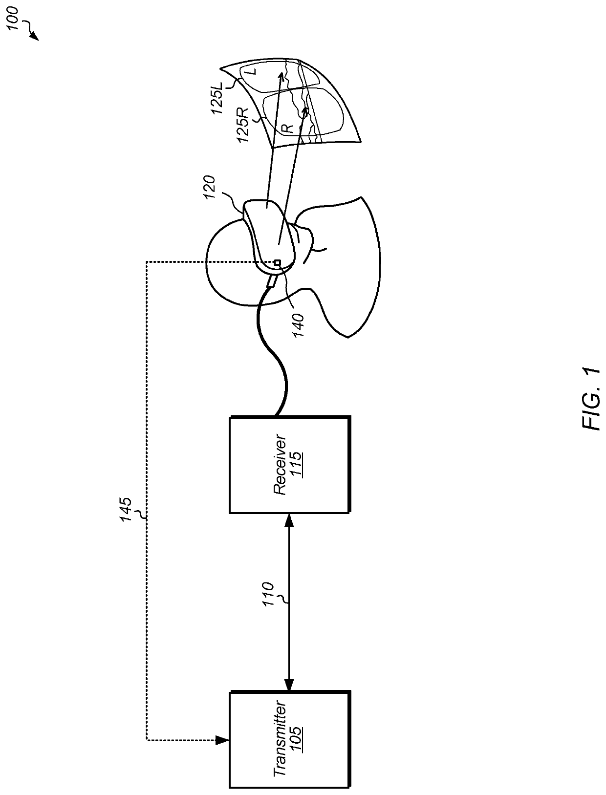
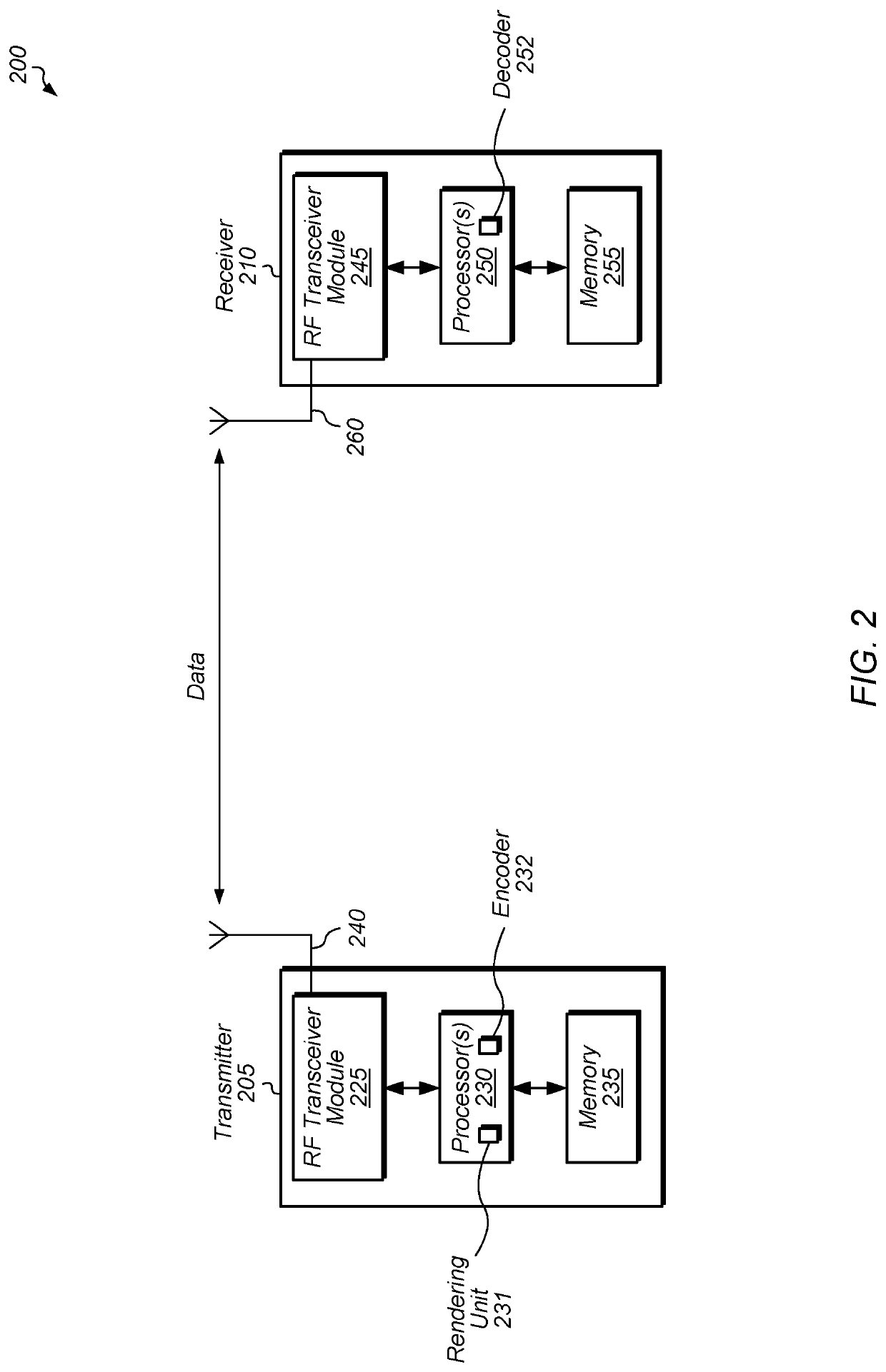
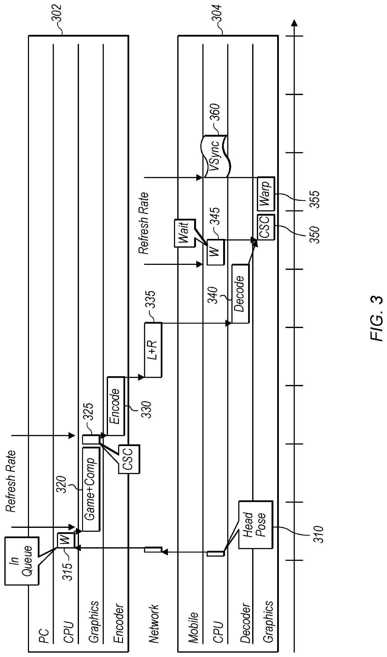
Systems, apparatuses, and methods for reducing latency for wireless virtual and augmented reality applications are disclosed. A virtual reality (VR) or augmented reality (AR) system includes a transmitter rendering, encoding, and sending video frames to a receiver coupled to a head-mounted display (HMD). In one scenario, rather than waiting until the entire frame is encoded before sending the frame to the receiver, the transmitter sends an encoded left-eye portion to the receiver while the right-eye portion is being encoded. In another scenario, the frame is partitioned into a plurality of slices, and each slice is encoded and then sent to the receiver while the next slice is being encoded. In a further scenario, each slice is being encoded while the next slice is being rendered. In a still further scenario, each slice is prepared for presentation by the receiver while the next slice is being decoded by the receiver.

Description

BACKGROUNDDescription of the Related Art[0001]In order to create an immersive environment for the user, virtual reality (VR) and artificial reality (AR) video streaming applications typically require high resolution and high frame-rates, which equates to high data-rates. Standard video codecs like H.264 and High Efficiency Video Coding (HEVC) are commonly used to encode the video frames rendered as part of the VR or AR application. As resolutions and refresh rates of VR and AR displays increase, the latency required for rendering, encoding, transmitting, decoding, and preparing frames for display becomes a major limiting factor.[0002]Additional elements in wireless VR and AR systems introduce more latency. This latency consists of the relatively constant latency of operations performed by an encoder and a decoder as well as the variable latency of wireless transmission. This additional latency is not present in traditional wired VR and AR systems and can be significant, causing rend...

Claims


Application Information

Patent Timeline
Patent Type & Authority Patents(United States)
IPC IPC(8): H04N19/436H04N19/42H04N19/174
CPCH04N19/436H04N19/174H04N19/439H04N13/161H04N13/332H04N13/194
Inventor MIRONOV, MIKHAILKOLESNIK, GENNADIYSINIAVINE, PAVEL
Owner ATI TECH INC
Learn More