Eureka AIR delivers breakthrough ideas for toughest innovation challenges, trusted by R&D personnel around the world.

Vehicle structure sub-unit, with crash-box modules

a technology of vehicle structure and sub-unit, applied in the field of vehicle structure, can solve the problems of laborious and costly construction, affecting the performance of the vehicle, and the impact can vary, so as to improve the capacity of the entire structure, improve the stability of the vehicle, and reduce the effect of weigh

Active Publication Date: 2021-07-27
CENT RICERCHE FIAT SCPA
View PDF45 Cites 1 Cited by
  • Summary
  • Abstract
  • Description
  • Claims
  • Application Information

AI Technical Summary

Benefits of technology

[0011]An object of the present invention is to provide a vehicle structure sub-unit of the type indicated at the beginning of the present description which has a high impact energy absorption capacity, without involving a greater risk of breakage, thanks in particular to a better distribution of the stresses in the areas connecting the cross-member and the crash-box modules.
[0012]Another object of the invention is to provide the aforesaid objective with a structure having an extremely simple configuration, which involves correspondingly simple and economical manufacturing operations.
[0013]Another object of the invention is that of achieving the aforesaid objectives without requiring any appreciable increase in the weight of the structure with respect to the known solutions, indeed possibly allowing a reduction in weight.

Problems solved by technology

These sub-units must be designed in such a way as to obtain the required energy absorption capacity without, however, excessively increasing the weight of the structure and without adopting complex configurations that result in a laborious and costly construction.
The problem is not easy to solve, given in particular the criticality of the connection area between the crash-box modules and the cross-member (due to the concentration of stress in this area) and also taking into account the fact that the impact is not generally evenly distributed throughout the structure, and that the intensity of the impact can vary greatly from case to case.

Method used


Image

  • Vehicle structure sub-unit, with crash-box modules
  • Vehicle structure sub-unit, with crash-box modules
  • Vehicle structure sub-unit, with crash-box modules

Examples


Embodiment Construction

[0037]Further characteristics and advantages of the invention will become apparent from the description that follows with reference to the attached drawings, provided purely by way of non-limiting example, wherein:

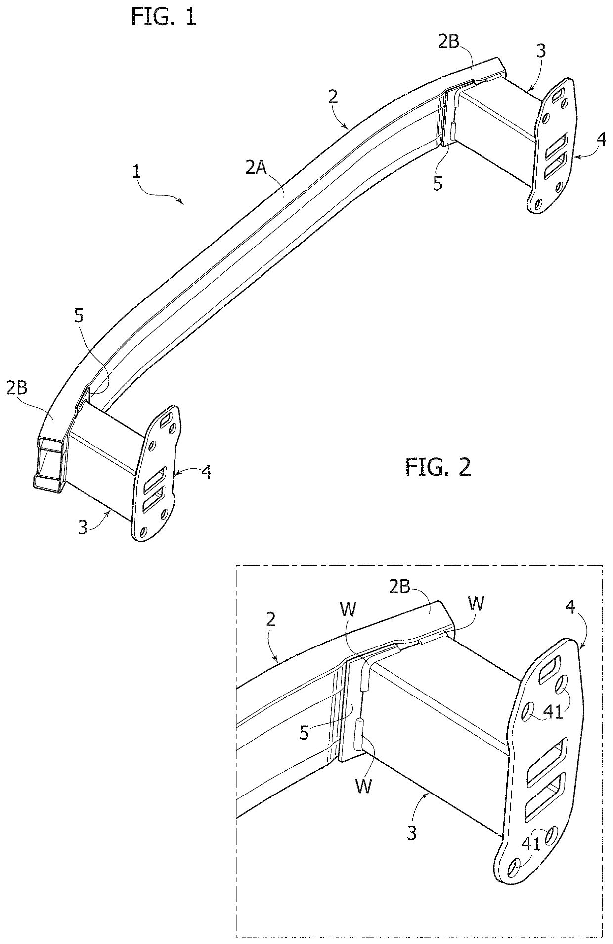
[0038]FIG. 1 is a perspective view of a vehicle structure sub-unit according to a preferred embodiment of the present invention,

[0039]FIG. 2 is a perspective view, on an enlarged scale, of a detail of FIG. 1,

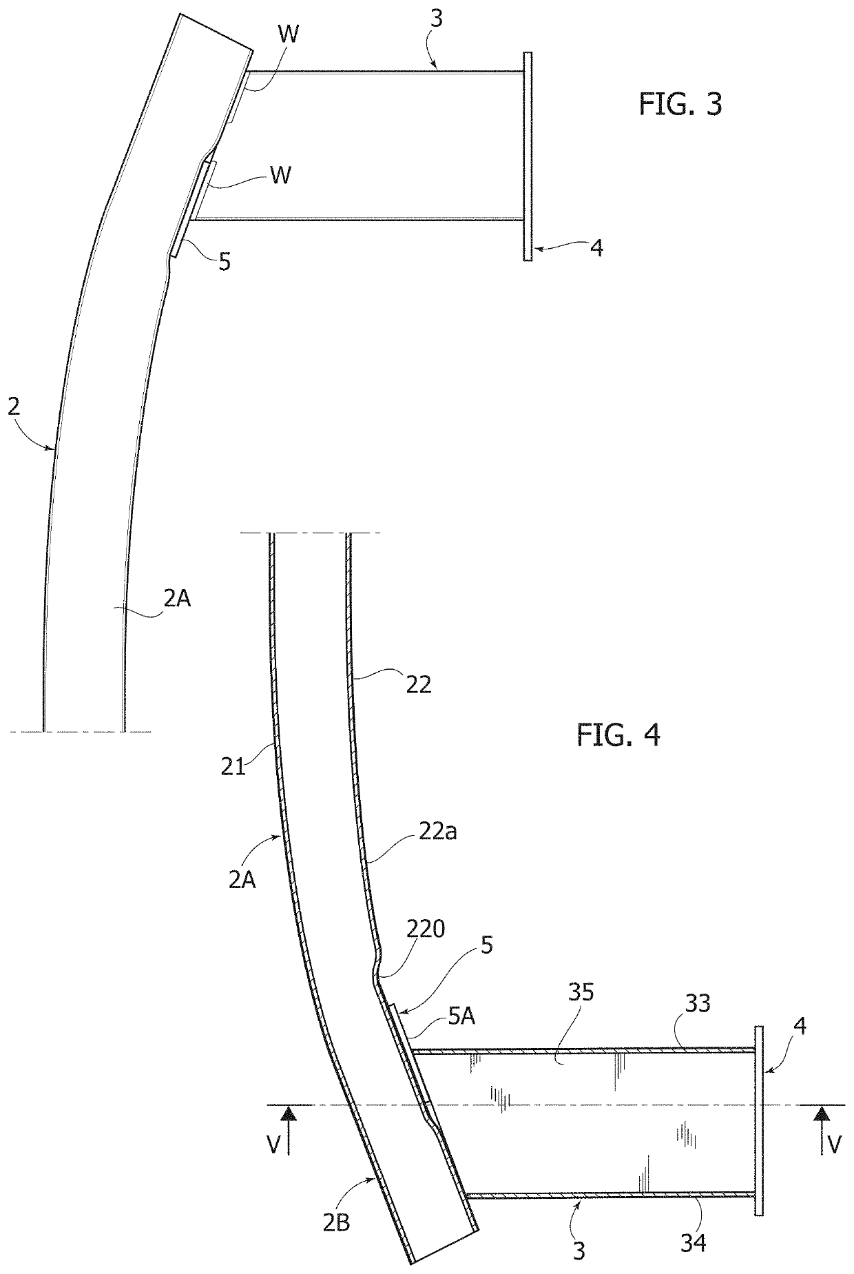
[0040]FIG. 3 is a plan view of a detail of FIG. 1,

[0041]FIG. 4 is a cross-sectional view along the line IV-IV of FIG. 5,

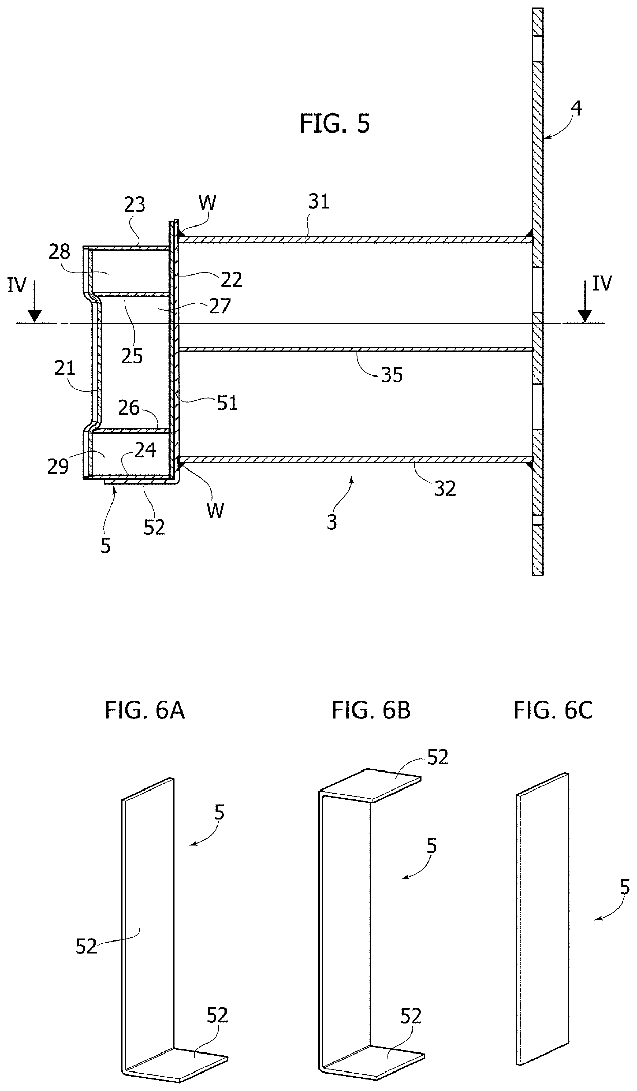
[0042]FIG. 5 is a cross-sectional view along the line V-V of FIG. 4,

[0043]FIGS. 6A, 6B, 6C are perspective views of three different embodiments of the reinforcement plate provided in the structure according to the invention, and

[0044]FIG. 7 is a perspective view of a single crash-box module.

[0045]In the drawings, the reference number 1 indicates—in its entirety—a sub-unit of a motor-vehicle structure, usable as a front module or rear module, with impa...


PUM


Abstract

A vehicle structure sub-unit includes a cross-member of metal material and two crash-box modules with their front surfaces welded or glued to the rear wall of the cross-member. A reinforcing metal plate is interposed between the front surface of at least one of the two crash-box modules and the rear wall. The rear wall has a depressed flat portion in which the reinforcing plate is received, in such a way that the surface of the reinforcing plate facing the crash-box module is substantially flush with the surface of the rear wall. A depressed portion of the rear wall is located in an offset position, closer to the center of the cross-member, with respect to the crash-box module, in such a way that the reinforcing plate is in contact only with a part of the front surface of the crash-box module, the remaining part of the front surface being in direct contact with the rear wall.

Description

CROSS REFERENCE TO RELATED APPLICATIONS[0001]This application claims priority from European Patent Application No. EP 18211857.0 filed on Dec. 12, 2018, the entire disclosure of which is incorporated herein by reference.FIELD OF THE INVENTION[0002]The present invention relates to vehicle structures and relates in particular to a vehicle structure sub-unit configured as a structure capable of absorbing at least part of the energy of an impact, and usable as a front module and / or as a rear module of a vehicle structure.[0003]In particular, the invention relates to a known type of vehicle structure sub-unit comprising:[0004]a cross-member made of metal material, including, with reference to the mounted condition on the vehicle, a front wall, a rear wall, an upper wall and a lower wall (one or more internal partitions may also be provided),[0005]two crash-box modules welded or glued to the rear wall of the cross-member, near two opposite ends of the cross-member and extending in a direc...

Claims


Application Information

Patent Timeline
Patent Type & Authority Patents(United States)
IPC IPC(8): B60J7/00B60R19/18B60R19/04B60R19/34B62D21/15
CPCB60R19/18B60R19/04B60R19/34B60R2019/182B60R2019/186B62D21/152B60R2019/1806B60R2019/1813
Inventor MENEGAZZI, STEFANO
Owner CENT RICERCHE FIAT SCPA
Why Eureka
Eureka Blog
Learn More