
Display device and method of driving same

a technology of a display device and a driver, applied in the direction of static indicating devices, instruments, etc., can solve the problems of increasing the duration of one frame, increasing the time allocated to black image writing within one frame, and not being suitable for high-speed operation, so as to reduce the motion picture response time (mprt), effectively erase the image of the previous frame, and improve the effect of motion blur

Active Publication Date: 2021-08-03
LG DISPLAY CO LTD
View PDF6 Cites 4 Cited by
  • Summary
  • Abstract
  • Description
  • Claims
  • Application Information

AI Technical Summary

Benefits of technology

[0004]A black image insertion technique can be used in organic light-emitting diode displays in to reduce a motion picture response time (MPRT) and improve motion blur. The black image insertion technique displays a black image between neighboring image frames to effectively erase the image of the previous frame.
[0007]Accordingly, the disclosure provides a display device which is enhanced or optimized for high-speed operation and can be used to solve the problem of insufficient input image charging time and poor picture quality due to deterioration caused by black image insertion which is used to enhance or improve a motion picture response time, and a method of driving the same.

Problems solved by technology

The black image insertion technique writes all input images corresponding to one frame and then inserts a black image and thus increases the duration of one frame and is not suitable for high-speed operation.
Further, since the black image insertion technique sequentially writes black images in units of pixel line, a time allocated to black image writing within one frame is long and thus an input image charging time is insufficient.
In addition, when the black image insertion technique is used, bright lines having higher luminance than normal luminance or dark lines having lower luminance than the normal luminance are generated in specific pixel lines when input images are reproduced, deteriorating picture quality.

Method used


Image

  • Display device and method of driving same
  • Display device and method of driving same
  • Display device and method of driving same

Examples


Embodiment Construction

[0027]The advantages, features and methods for accomplishing the same of the disclosure will become more apparent through the following detailed description with respect to the accompanying drawings. However, the disclosure is not limited by embodiments described blow and is implemented in various different forms, and the embodiments are provided so that this disclosure will be thorough and complete, and will fully convey the scope of the disclosure to those skilled in the art. The disclosure is defined by the scope of the claims.

[0028]Shapes, sizes, ratios, angles, numbers, etc., shown in the figures to describe embodiments of the disclosure are exemplary and thus are not limited to particulars shown in the figures. Like numbers refer to like elements throughout the specification. It will be further understood that when the terms “include”, “have” and “comprise” are used in this specification, other parts may be added unless “˜only” is used. An element described in the singular for...


PUM


Abstract

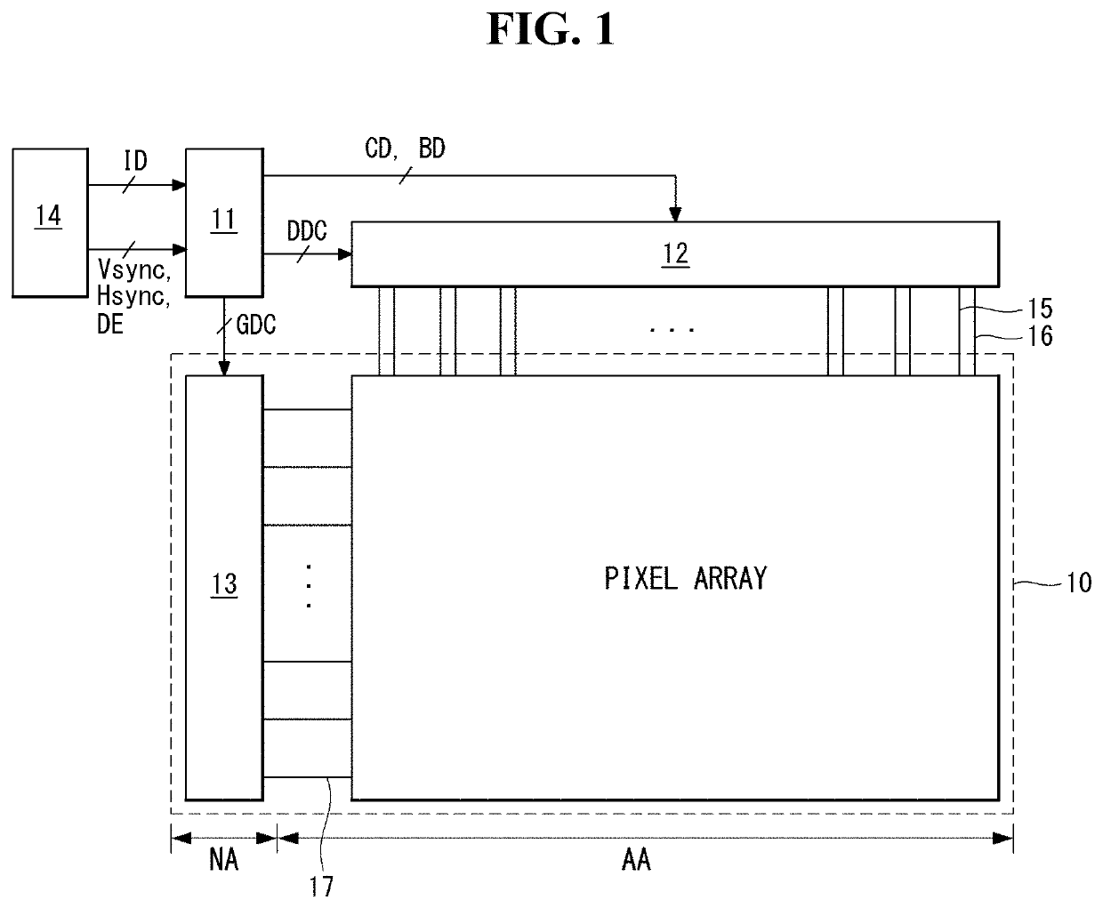
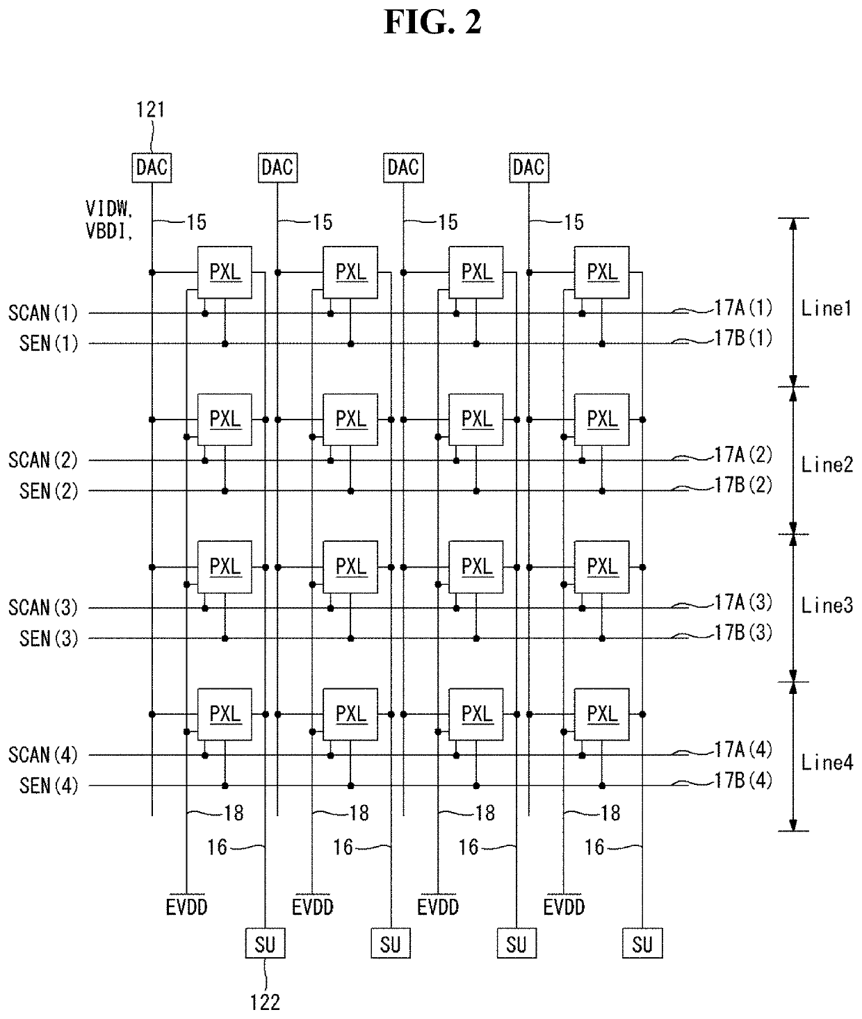
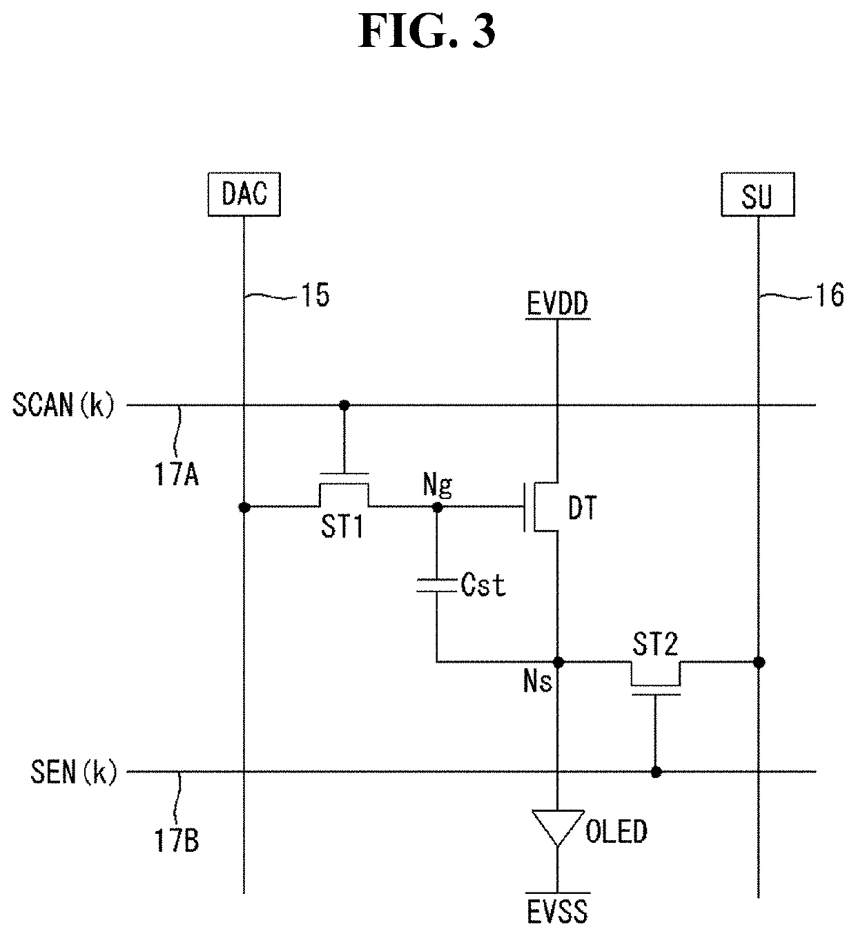
A display device and a method of driving the same are provided. The display device according to an embodiment of the disclosure includes: a display panel including a plurality of pixel lines in an area A, an area B, and an area C; a panel driver configured to: supply input image data to pixel lines in the area A during a first period; supply black image data to pixel lines in the area B during a second period following the first period; and supply input image data to pixel lines in the area C during a third period following the second period; and a timing controller configured to adjust a first input image data to be supplied to a last pixel line in the area A to a first adjusted data based on a first compensation table.

Description

CROSS-REFERENCE TO RELATED APPLICATION[0001]This application claims the benefit of Korea Patent Application No. 10-2018-0139434, filed on Nov. 13, 2018, which are incorporated herein by reference for all purposes as if fully set forth herein.BACKGROUNDTechnical Field[0002]The disclosure relates to a display device and a method of driving the same.Description of the Related Art[0003]Flat display devices are widely used for portable computers such as laptop computers and PDAs and cellular phones as well as desktop computers since their sizes and weights can be reduced. Such display devices include a liquid crystal display (LCD), a plasma display panel (PDP), an organic light-emitting diode display, and the like. Particularly, an active matrix type organic light emitting diode display including organic light-emitting diodes (OLEDs) which spontaneously emit light has the advantages of a high response speed, high emission efficiency, high luminance and a wide viewing angle.BRIEF SUMMARY[...

Claims


Application Information

Patent Timeline
Patent Type & Authority Patents(United States)
IPC IPC(8): G09G3/3258G09G3/3266G09G3/3291
CPCG09G3/3258G09G3/3266G09G3/3291G09G2310/027G09G2320/0285G09G3/3225G09G3/32G09G2320/043G09G2320/0295G09G3/3233G09G2320/0261G09G2320/0252G09G2320/106G09G2310/08G09G2320/0257G09G2320/0626G09G2310/0221G09G2320/0686
Inventor KIM, YOUNGHOKOO, SUNGJOJEONG, YANGSEOK
Owner LG DISPLAY CO LTD
Learn More