Double wringing water removal method for tire rubber component

A rubber and tire technology, applied in the field of rubber tire production, can solve the problems of sponge damage, extrusion treatment, small contact area, etc., and achieve the effect of reducing industrial accidents, prolonging service life, and ensuring water absorption efficiency

Active Publication Date: 2017-01-11
山东云特信息科技有限公司
View PDF9 Cites 2 Cited by
  • Summary
  • Abstract
  • Description
  • Claims
  • Application Information

AI Technical Summary

Problems solved by technology

Compared with patent ZL201020169996.6, patent ZL201120555189.2 increases the contact area between sponge and rubber components, but it still belongs to line contact, and the contact area is still small
In addition, there is no relative displacement between the contact surface of the sponge and the rubber component, the water absorption efficiency is not high, and the water in the sponge roller is not squeezed out. After a long time, the upper surface of the rubber components such as the tread and the sidewall will be damaged. Moisture cannot be absorbed
At present, most of the methods of installing tire rubber components into the sponge dewatering device are directly pulled and dragged by human hands, which will cause damage to the sponge and easily cause industrial accidents

Method used


Image

  • Double wringing water removal method for tire rubber component
  • Double wringing water removal method for tire rubber component
  • Double wringing water removal method for tire rubber component

Examples


Embodiment 1

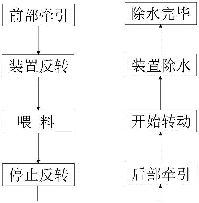
[0027] The technical process of the double-squeezing water-removing method for tire rubber components related to the present embodiment comprises the following steps:

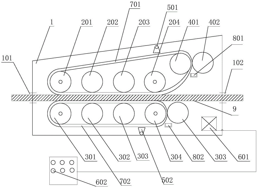
[0028] (1): front traction: pull the tire rubber assembly 9 from other conveying devices in front of the double squeeze water removal device to the material channel inlet 101 of the double squeeze water remover device;

[0029] (2): device reversal: the drive device 601 is set to reverse by the drive control device 602, and the drive device 601 is started;

[0030] (3): Feeding: dry the water at the end of the tire rubber assembly 9, insert the tire rubber assembly 9 into the middle gap formed by the crawler-shaped upper sponge 701 and the crawler-shaped lower sponge 702, and make the tire rubber assembly 9 follow the The crawler-shaped sponge 701 and the crawler-shaped lower sponge 702 move to the material channel outlet 102;

[0031] (4): stop reversing: turn off the driving device 601 through the driving co...

Embodiment 2

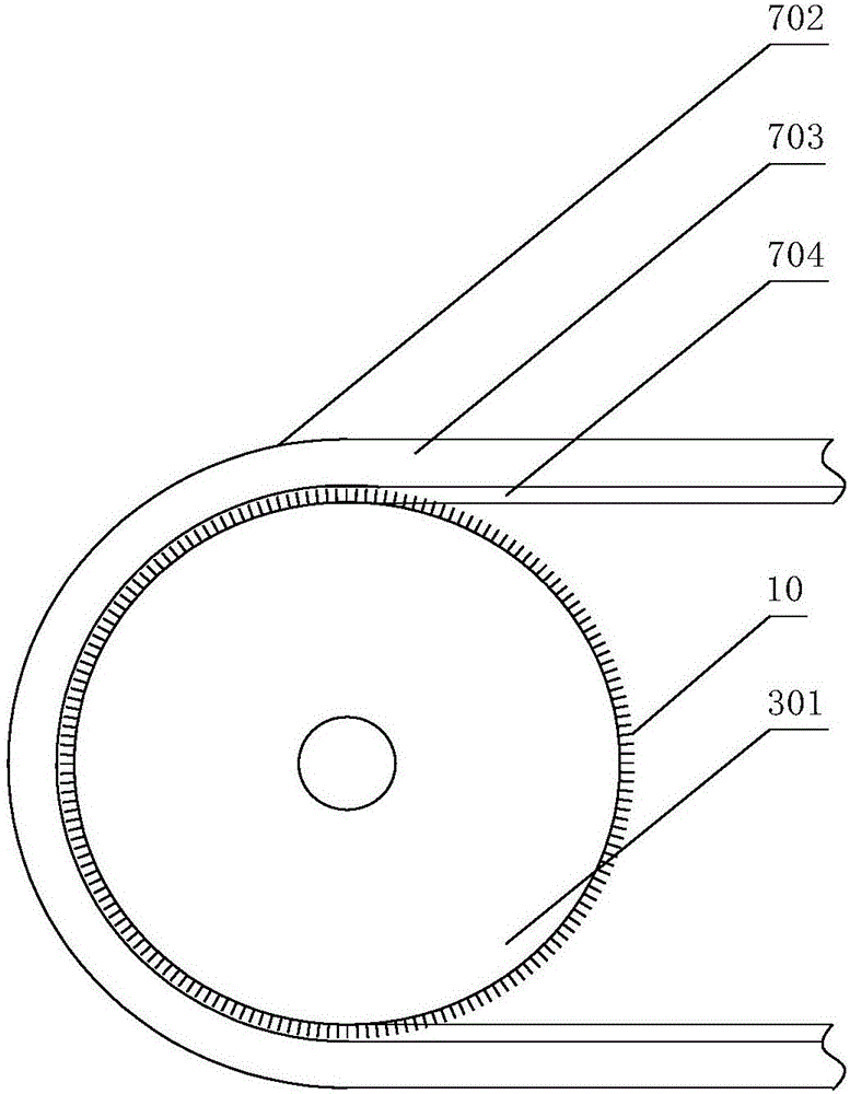
[0040] The double-squeezing and water-removing device for tire rubber components involved in this embodiment has the same main structure as that of Embodiment 1, except that the first upper supporting roller 201, the first upper squeezing roller 401, the first The surface of the lower supporting roller 301 and the fourth lower supporting roller 304 is distributed with spikes 10, the second upper supporting roller 202, the third upper supporting roller 203, the fourth upper supporting roller 204, the second lower supporting roller 302, the third lower supporting roller The surfaces of the supporting roller 303, the second upper squeezing roller 402, and the lower squeezing roller 403 are smooth. The track-shaped upper sponge 701 and the track-shaped lower sponge 702 all include a sponge layer 703 and a cord layer 704. The thickness of the cord layer 704 is 1.1 times the length of the spike 10. The cord layer 704 is connected to the first upper support roller 201 and the second u...

Embodiment 3

[0042] The double squeeze water removal device for tire rubber components involved in this embodiment has the same main structure as that of Embodiment 1, the difference is that the upper water tank 801 is a strip-shaped long groove, and the upper water tank 801 is The long side is parallel to the axis of the first upper water squeezing roller 401, the length of the long side of the upper water tank 801 is greater than the width of the track-shaped sponge 701, and the upper water tank 801 bottom is connected with an upper drain pipe 803. This design of timely squeezing and drying the track-shaped sponge 701 that has absorbed moisture can keep the track-shaped sponge 701 in a relatively dry state and maintain high water absorption and water removal efficiency. The lower receiving water tank 802 is located below the gap between the fourth lower support roller 304 and the lower squeezing water roller 403; the lower receiving water tank 802 is a strip-shaped long groove, and the lo...


PUM


Abstract

The invention relates to a double wringing water removal method for a tire rubber component. The double wringing water removal method comprises the steps of front traction, device reversal, feeding, reversal stop, rear traction, transmission beginning, device water removal and water removal completion. The method can reduce damage to a crawler shaped sponge during mounting of the rubber component and prolongs the service life of a device; a driving device reverses to allow the tire rubber component to pass through a double wringing water removal device; hands are prevented from stretching into the double wringing water removal device; industrial accidents are reduced; an upper and lower surface friction and contact mode of the two crawler shaped sponges and the tire rubber component is adopted; the upper and lower sponges are subjected to wringing treatment; continuous water absorption efficiency of the sponge is ensured; and water on the surface of the rubber component can be wiped efficiently and cleanly.

Description

[0001] Technical field: [0002] The invention relates to the technical field of rubber tire production, in particular to a double-squeeze dewatering method for tire rubber components, which efficiently and cleanly wipes off the moisture on the surface of the rubber components by friction between the sponge and the upper and lower surfaces of the tread. [0003] Background technique: [0004] In the production process of existing tires, due to the high temperature of rubber components such as sidewalls and treads after being extruded from the machine head, cooling is required. Most tire manufacturers use water cooling to cool down, and sidewalls and treads are cooled by spraying. After that, water droplets and water stains will adhere to the upper and lower surfaces. Due to the technical requirements, there should be no moisture when the components are assembled later, otherwise it will affect the bonding effect of the tire; on the other hand, when rubber components such as tre...

Claims


Application Information

Patent Timeline
Patent Type & Authority Applications(China)
IPC IPC(8): B29C47/08B29C37/00
CPCB29C37/0092B29C48/274
Inventor 王舜华张云飞凌梵奚曹侠郭继艳
Owner 山东云特信息科技有限公司
Why Eureka
Try Eureka