High-power, weather resistant platform for a test system for testing collision or near-collision situations

a technology for collisions and near collisions, applied in vehicle testing, measurement devices, instruments, etc., can solve the problem of not being able to carry out realistic experiments, and achieve the effect of different heat extension coefficients, high form stability of the platform, and high heat extension coefficient of the material

Active Publication Date: 2021-08-17
4ACTIVESYST
View PDF57 Cites 0 Cited by
  • Summary
  • Abstract
  • Description
  • Claims
  • Application Information

AI Technical Summary

Benefits of technology

[0017]The at least one roller element may be arranged at the bottom surface. In a preferred embodiment, three or four roller elements may be arranged at the base body, namely spaced at a distance at the bottom surface. Thus, a high rolling stability and a good controllability (or steerability) of the platform may be given. The roller element may consist, for example, of rubber rollers, duroplastic plastics rollers or plastic material rollers.
[0072]According to a further exemplary embodiment, two opposing carrier elements respectively may have further coupling elements. The carrier structure in addition may have at least one connection carrier, which may, with its ends, fixed displaceably (along its extension direction) respectively in one of the coupling elements. The connection carrier thus may form a cross-brace, by which the carrier structure may become more warp resistant.

Problems solved by technology

In doing so, it is necessary that the components and devices of the test system are formed inconspicuously such that the test system does not influence the assistance system during the test, because otherwise no realistic experiments can be carried out.

Method used


Image

  • High-power, weather resistant platform for a test system for testing collision or near-collision situations
  • High-power, weather resistant platform for a test system for testing collision or near-collision situations
  • High-power, weather resistant platform for a test system for testing collision or near-collision situations

Examples


Embodiment Construction

[0080]Equal or similar components in different figures are provided with same reference numerals. The illustrations in the figures are schematic.

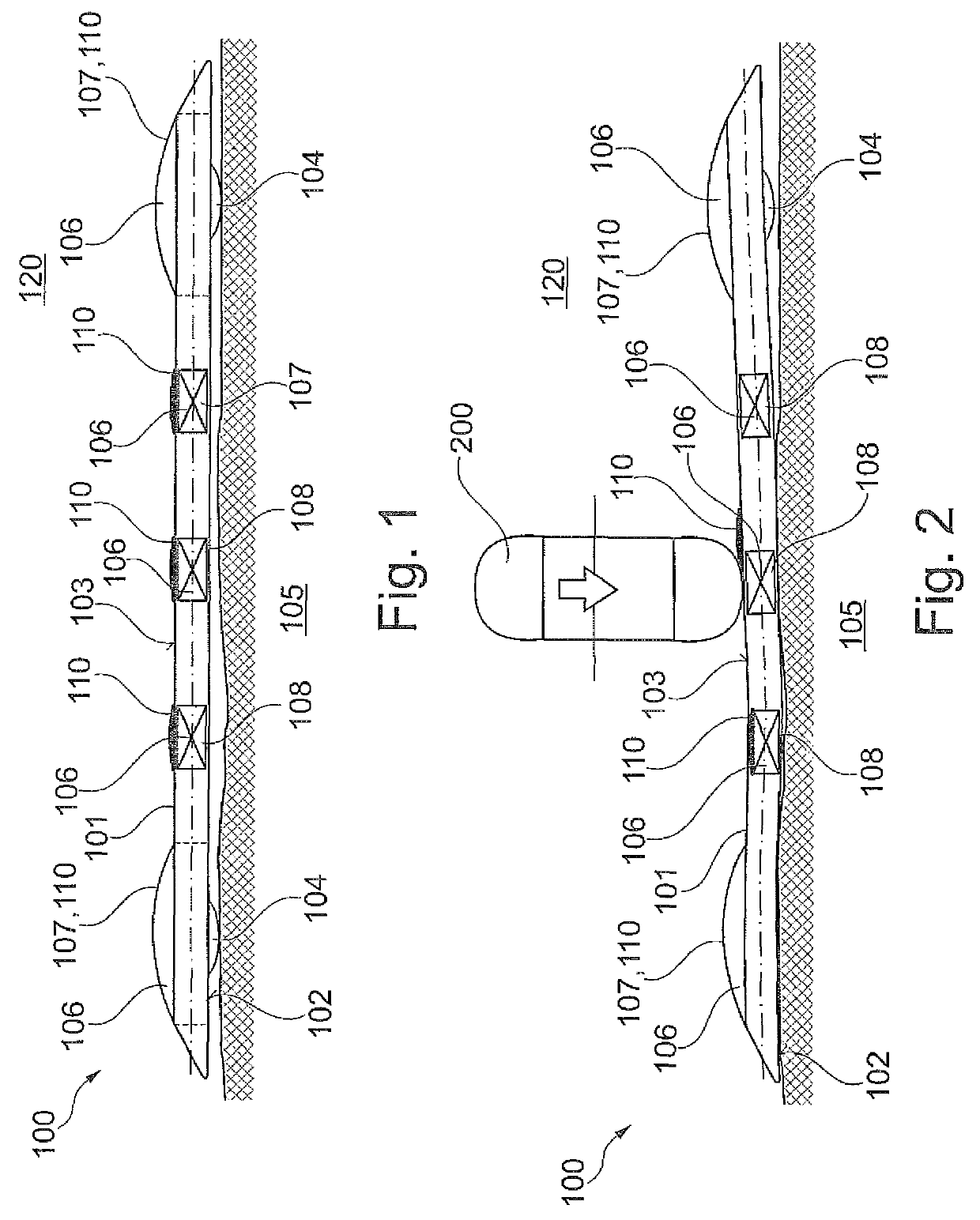
[0081]FIG. 1 and FIG. 2 show a platform 100 for testing collisions or near-collision situations between a collision body, in particular a vehicle, and a test object. The platform 100 may have a base body 101, which may have a bottom surface 102 and an attachment surface 103 that may be formed opposite to the bottom surface 102, wherein an attachment device 109 may be formed on the attachment surface 103 for fixing the test object. Furthermore, the platform 100 may have at least one roller element 104, which may be arranged at the bottom surface 102, wherein the roller element 104 may be formed such that the base body 101 may be movable along a ground 105 by the roller element.

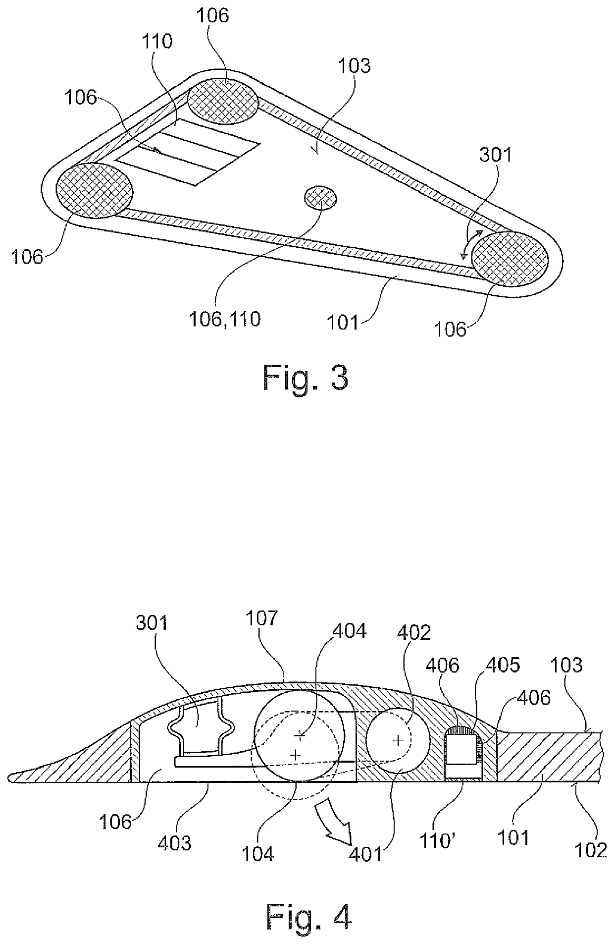
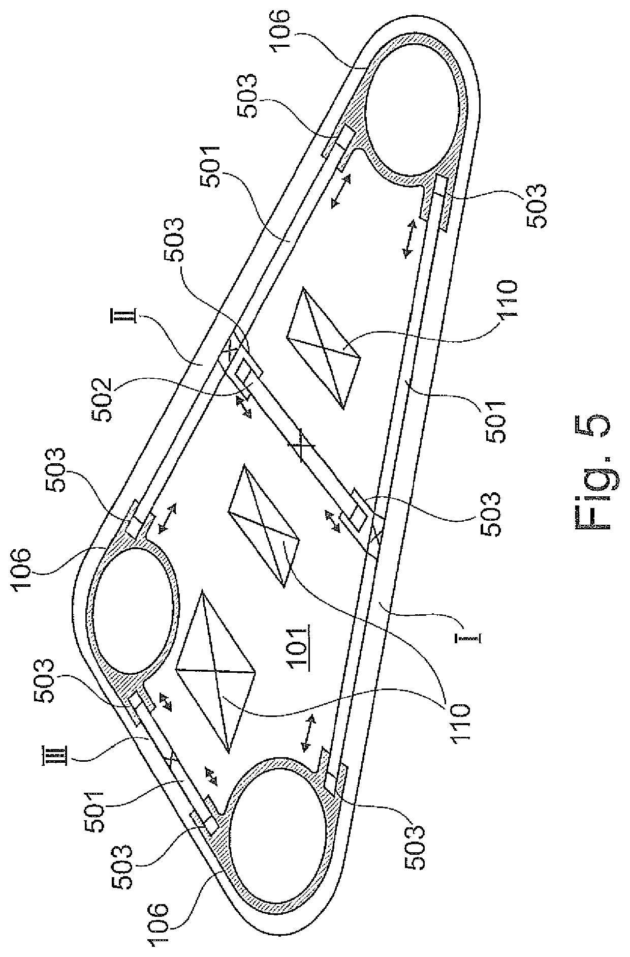
[0082]The platform 100 may have an installation box 106 having an installation volume, which may be arranged in a receiving opening of the base body 101. The installat...


PUM


Abstract

The present invention relates to a platform for testing collisions or near-collision situations between a collision body, in particular a vehicle, and a test object. The platform has a base body, which has a bottom surface and an attachment surface formed opposite to the bottom surface, wherein an attachment device is formed on the attachment surface for attaching the test object. Furthermore, the platform has at least one roller element, which is arranged at the bottom surface, wherein the roller element configured such that the base body is displaceable along a ground by the roller element. An installation box having an installation volume is arranged in a receiving opening of the base body, wherein the installation box is conceived in the receiving opening of the base body such that a temperature control region of the installation box is in contact with a surroundings of the base body. The temperature control region is formed of a material, which has a greater heat conductivity coefficient than a material of the base body.

Description

CROSS-REFERENCE TO RELATED APPLICATION[0001]The present application is a national phase application derived from the international patent application no. PCT / EP2017 / 066808 filed Jul. 5, 2017, which in turn benefits from the filing date of the German patent application no. DE 10 2016 112 4273, filed Jul. 6, 2016, both of which are incorporated herein by reference in their entirety.TECHNICAL AREA[0002]The present invention relates to platforms for testing collisions or near-collision situations between a collision body, in particular a vehicle, and a test object, as well as a method for manufacturing platforms.BACKGROUND OF THE INVENTION[0003]In modern automotive technology, more and more assistance systems come into operation, which systems actively monitor the surroundings of the vehicle and passively or actively intervene in the steerage of the vehicle. Assistance systems therefore have to be subjected to tests to the full extent in order to prevent misjudgements of the assistance ...

Claims


Application Information

Patent Timeline
Patent Type & Authority Patents(United States)
IPC IPC(8): G01M17/007
CPCG01M17/0078
Inventor HAFELLNER, REINHARDFRITZ, MARTIN
Owner 4ACTIVESYST
Why Eureka
Try Eureka