Vehicle air conditioning unit with heat exchanger arranged in suction side

a technology of heat exchanger and vehicle air conditioner, which is applied in the direction of vehicle components, vehicle heating/cooling devices, transportation and packaging, etc., can solve the problems of increased technical expenditure, higher technical complexity, and increased cost, so as to reduce space requirements, increase heating and cooling capacity, and reduce installation space requirements

Active Publication Date: 2021-08-24
HANON SYST
View PDF6 Cites 0 Cited by
  • Summary
  • Abstract
  • Description
  • Claims
  • Application Information

AI Technical Summary

Benefits of technology

[0014]It is especially preferred for the preheat zone of the heating heat exchanger and the evaporator to be disposed in parallel in the vehicle climate control unit. The air flowing toward the vehicle climate control unit herein flows parallel through the preheat zone of the heating heat exchanger and through the evaporator and the air is consequently, where appropriate, less dehumidified than is the case with series connection of evaporator and heating heat exchanger. However, the advantage of the connection in parallel frequently lies in an especially space-saving implementation of the vehicle climate control unit.
[0015]A significant advantage of the parallel disposition resides in a lower air-side pressure loss at temperature settings above “fully cold”. In this setting the lower pressure loss leads to reduced power requirements of the blower and, as a rule, also to lesser noise development in comparison to series connections at identical air quantity.
[0017]It is of advantage for a main temperature louver to be provided between the evaporator and the preheat zone of the heating heat exchanger. The main temperature louver controls herein the ratio of heated to cooled air. The disposition of the louver downstream of the heat exchangers and upstream of the blower enables the regulation of the ratio of warm and cold air into the blower across the louver position of the main temperature louver.
[0020]It can, alternatively, also be of advantage under certain conditions to implement the secondary temperature louver with a separate drive which subsequently results in the independent control of the reheat flow.
[0026]Especially advantageous is the lower installation space requirement of the vehicle climate control unit and the alternative utilization of the gained space in the vehicle. The installation space reduction is attainable due to the omission of the mixing chamber with the required built-in components for warm and cold air in the climate control unit whereby a considerable reduction of the space requirement is realized. Larger heat exchangers are moreover employable for increasing the heating and cooling capacities. Fewer resources for the development of the temperature regulation curves and of the climate control unit are also required which, overall, lowers the cost of the climate control unit and beyond that also reduces the susceptibility to damage or failure as well as the maintenance expenditures. Similarly, no resources are required for the development of different temperature strands in individual air outlets.

Problems solved by technology

In this configuration of the heat exchangers it is difficult to achieve thermal stratification at different air outlets of the climate control unit since the disposition of the heat exchangers in front of the blower leads to the formation of a mixed volume flow of cold and warm air in the blower which does not show any thermal stratification.
It is consequently not possible to provide an air volume flow with thermal stratification at the pressure side of the blower for the air outlets.
A significant disadvantage of this is that through the air blower a thorough mixing of the inflowing cold and warm air takes place and all pressure-side air outlets in the vehicle are consequently tempered alike.
As a rule, this contradicts the prevailing requirements of vehicle manufacturers who require different tempering and in particular thermal stratification at the air outlets of the vehicle climate control units.
Of disadvantage herein is that additional heat exchangers are employed leading to concomitantly higher technical expenditures and complexity and greater costs.

Method used


Image

  • Vehicle air conditioning unit with heat exchanger arranged in suction side

Examples


Embodiment Construction

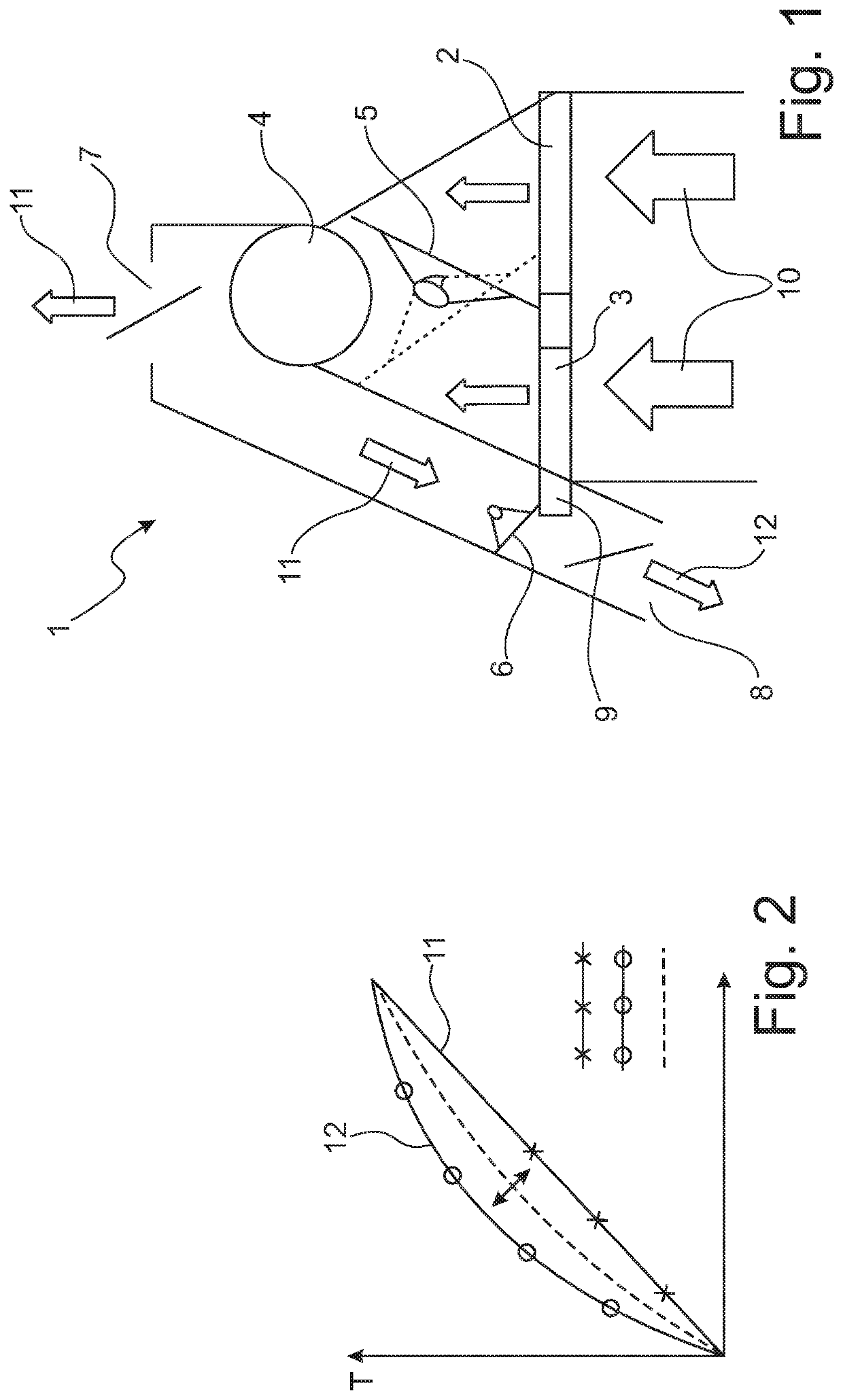
[0031]In FIG. 1 is depicted an implementation of a vehicle climate control unit 1 in which the suction-side disposition of the heat exchangers is realized. The vehicle climate control unit 1 comprises, firstly, an evaporator 2 and a heating heat exchanger with a preheat zone 3, The two heat exchangers are located at the suction side with respect to a blower 4, across which the climate control inflow 10 is suctioned into the vehicle climate control unit 1. The air of the climate control inflow 10 in the depicted implementation flows in parallel through the evaporator 2 and the preheat zone 3 of the heating heat exchanger. Between the two heat exchangers 2, 3 and the blower 4 is disposed a main temperature louver 5 that controls the ratio of the air volume flows as a function of the louver position.

[0032]The complete heating of the air flowing toward the blower 4 as well as also the complete cooling of the air flowing toward the blower 4 as well as also proportional mixing of cooled a...


PUM


Abstract

A vehicle climate control unit with an evaporator, a heating heat exchanger as well as a blower, characterized in that, in the direction of the air flow, are disposed, upstream of the blower on the suction side, the evaporator and the heating heat exchanger, and that an additional heating heat exchanger is disposed downstream of the blower on the pressure side.

Description

[0001]This application claims priority from German Patent Application No. 102018113176.3 filed on Jun. 4, 2018. The entire contents of this application is incorporated herein by reference in its entirety.FIELD OF THE INVENTION[0002]The invention relates to a vehicle climate control unit with heat exchangers that, with respect to the blower, are disposed at the suction side. The vehicle climate control unit is especially well suited to realize also with this construction type an adjustable thermal stratification at the air outlets.BACKGROUND OF THE INVENTION[0003]Prior art discloses vehicle climate control units in the most diverse implementations. With respect to the air volume flow, the heat exchangers of the climate control unit as well as the evaporator and the heating heat exchangers are typically located on the pressure side of the blower or ventilator. However, there are also vehicle climate control units known in which the heat exchangers, in contrast to the typical configura...

Claims


Application Information

Patent Timeline
Patent Type & Authority Patents(United States)
IPC IPC(8): B60H1/00B60H1/32
CPCB60H1/00464B60H1/00328B60H1/00671B60H1/3202B60H1/00028B60H1/00057B60H1/00521B60H1/00842B60H2001/00107
Inventor HANDWERK, DETLEF
Owner HANON SYST
Why Eureka
Try Eureka