
Dehumidification device and dehumidification method for pipeline

A pipeline and dehumidification unit technology, applied in the pipeline system, dry gas layout, pipeline heating/cooling, etc., can solve the problems of low automation, reduce labor intensity, avoid excessive dehumidification, and use safe and reliable effects

Inactive Publication Date: 2021-03-23
CHANGSHA GREE HVAC EQUIP CO LTD +1
View PDF10 Cites 0 Cited by
  • Summary
  • Abstract
  • Description
  • Claims
  • Application Information

AI Technical Summary

Problems solved by technology

[0004] In order to solve all or part of the above problems, the purpose of the present invention is to provide a dehumidification device and dehumidification method for pipelines, which are used to solve the problem of low automation in the dehumidification process of pipelines, which can not only reduce the labor intensity of operators, but also improve Dehumidification efficiency can also prevent energy waste and reduce the implementation cost of pipeline dehumidification

Method used


Image

  • Dehumidification device and dehumidification method for pipeline
  • Dehumidification device and dehumidification method for pipeline
  • Dehumidification device and dehumidification method for pipeline

Examples


Embodiment Construction

[0022] The present invention will be further described below in conjunction with accompanying drawing.

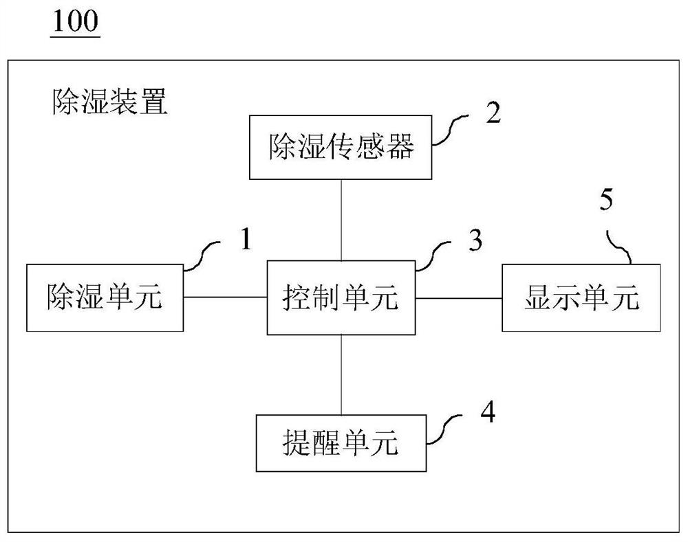
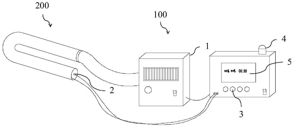
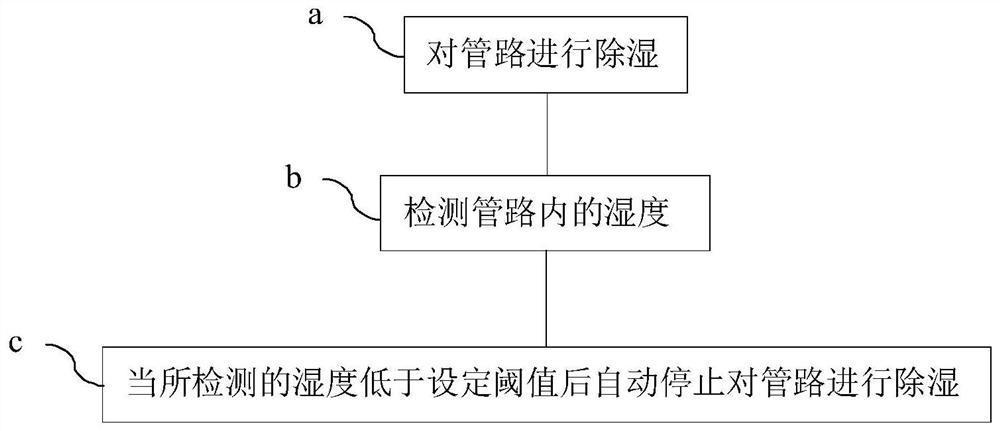
[0023] figure 1 It is a schematic structural diagram of a dehumidification device used in pipeline 200 according to an embodiment of the present invention; figure 2 It is a structural schematic diagram of the dehumidification device used for the pipeline 200 in the use state of the embodiment of the present invention. Such as figure 1 and figure 2 As shown, the embodiment of the present invention provides a dehumidification device 100 for a pipeline 200 , the pipeline 200 is preferably an air conditioning pipeline 200 , and the dehumidification device 100 includes a dehumidification unit 1 , a humidity sensor 2 and a control unit 3 . The dehumidification unit 1 can be connected with the pipeline 200 and dehumidify the inside of the pipeline 200 . The humidity sensor 2 is used to detect the humidity in the pipeline 200 . The control unit 3 is connected to both the deh...


PUM


Abstract

The invention relates to a dehumidification device and dehumidification method for a pipeline. The dehumidification device for the pipeline comprises a dehumidification unit, a humidity sensor and a control unit; the dehumidification unit can be connected to the pipeline; the humidity sensor is used for detecting the humidity in the pipeline; and the control unit is connected to the dehumidification unit and the humidity sensor; wherein the control unit is configured to be capable of turning off the dehumidification unit according to a measurement result of the humidity sensor. According to the dehumidification device and dehumidification method for the pipeline disclosed by the invention, the labor intensity of operators can be greatly reduced, the dehumidification efficiency is improved,excessive dehumidification caused by carelessness of the operators can be effectively avoided, thereby energy waste is effectively prevented, and the implementation cost of pipeline dehumidificationis reduced.

Description

technical field [0001] The invention belongs to the technical field of pipeline dehumidification, and in particular relates to a dehumidification device for pipelines and a dehumidification method for pipelines. Background technique [0002] In recent years, with the continuous development and improvement of industrial technology, especially the continuous development and integration of mechanical manufacturing technology and electrical engineering technology, the degree of automation in the field of mechanical manufacturing has become higher and higher. However, it should be noted that although the main production process of manufacturing enterprises has basically realized automatic production, the automation degree of the typical terminal production link of pipeline dehumidification, especially the dehumidification process of air conditioning pipeline is still very low. [0003] After the air conditioner is assembled, it is necessary to add water and pressure to test wheth...

Claims


Application Information

Patent Timeline
Patent Type & Authority Applications(China)
IPC IPC(8): F26B21/00F26B25/22F17D5/00F16L53/35
CPCF26B21/001F26B21/004F26B25/22F17D5/00F16L53/35
Inventor 王晓彬邓国波彭小兵王俊
Owner CHANGSHA GREE HVAC EQUIP CO LTD
Learn More