Mechatronic lock system

a mechatronic lock and lock technology, applied in non-mechanical controls, instruments, building constructions, etc., can solve the problems of user lockout, significant increase in cost and complexity, backup options however require additional (dedicated) hardware, etc., and achieve the effect of reducing the total cost of installation and high security level

Active Publication Date: 2021-08-31
BOLD SECURITY TECH BV
View PDF7 Cites 0 Cited by
  • Summary
  • Abstract
  • Description
  • Claims
  • Application Information

AI Technical Summary

Benefits of technology

[0014]It's yet a further objective of the described invention to provide an improved mechatronic lock system which is able to maintain a high level of security by providing as little feedback as possible to the user by its user interface.
[0042]With respect to a preferred user interaction method the most important boundary condition is ease-of-use which can be divided in two aspects; easy to execute and an easy to interpret / learn.

Problems solved by technology

Nevertheless, solely relying on smartphone operation is not preferred as the smartphone battery can be empty or the smartphone can get stolen, lost, forgotten or temporarily unavailable, leaving the user locked out.
Such backup options however require additional (dedicated) hardware.
One of these disadvantages is that electronic components e.g. sensors, buttons and the like need to be added in the outer knob in order to detect the distinct angular position of the outer knob and for the confirming user action.
Such protection functions result in a significant increase in cost and complexity and will adversely affect robustness in operation and digital and mechanical security.
Such a solution also comes at significant increase of cost and complexity while decreasing robustness and especially the mechanical security level.
However, even though this might be a suitable alternative for a double controlled lock system, with both the inner and the outer knob on one drive shaft and the cam being coupled and decoupled separately, it will be extremely difficult to create a single controlled variant due to the fact that both knobs are then rotating freely relative to each other.
Finally, a late-stage configurable lock system will be even more difficult if not impossible to create.
A disadvantage of known lock systems with such backup user interfaces is that such a user interface not only provides feedback to the user, e.g. about how the code should be entered or if the inputted code is correct, but also provide indications that give details about the code itself.
If for example a code can be entered through a keypad having only 5 keys, security details about the code are inherently disclosed thereby which thus lower the level of security that the lock system may provide.
The inventor however realized that this user interaction has a number of disadvantages, especially the feedback that is provided to the user through the user interface which not only reveals the fact that a user interface is present as backup system to the wireless control, but also has a negative effect on the level of security since information about the code such as length, suitable characters, etc. are revealed through the user interface.
manual force;uses limited energy and therefore has a long battery lifetime because
With such a system, additional costs for the described function are limited to the cost of applying the necessary sensors.
Various input methods are relatively unambiguous and involve little learning or interpretation from the user.

Method used


Image

  • Mechatronic lock system
  • Mechatronic lock system

Examples


Embodiment Construction

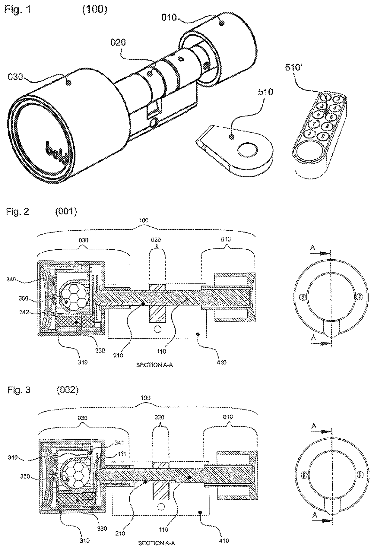
[0073]FIG. 1 schematically shows the disclosed lock system (100) with its main interfaces; the outer knob (010), the inner knob assembly (030), the door lock operating cam (020) and two example wireless communication devices (510, 510′). In this case a key fob and a numeric keypad respectively.

[0074]FIG. 2 schematically shows the disclosed lock system (100) as a double controlled variant (001); the outer knob (010) and inner knob assembly (030) are mechanically connected to the first shaft (110). The door lock operating cam (020) is mechanically connected to the second shaft (210).

[0075]Both knobs (010, 030) are freely rotating relative to the cylinder housing (410) and the second shaft (210). The inner knob assembly (030) consists of an inner knob housing (310), a mechatronic clutch unit (330), a wireless control unit (340) and an energy accumulator (350). An inertial sensor (342) is depicted as part of the wireless control unit (340) electronics assembly. A predetermined or progra...


PUM


Abstract

The present invention relates generally to mechatronic locks and more specifically, wireless mechatronic smart lock systems for locking doors which can be activated through a rotational movement of the outer knob. In an aspect, the present disclosure describes a specific user interaction method and technical solution for activating the lock system. The user applies a predetermined or programmable motion pattern of rotational movements or motion pattern of the outer knob. The input movements or motions are detected by a sensor and matched with reference motion pattern descriptions by the intelligent controller in the lock system. Upon a positive match the lock system will be activated.

Description

CROSS-REFERENCE TO RELATED APPLICATION[0001]This application is a national stage of Application No. PCT / NL2018 / 050305 filed May 9, 2018, which claims priority from Netherlands Application No. 2018876 filed May 9, 2017, which are both incorporated by reference in their entireties.TECHNICAL FIELD[0002]The present invention relates generally to mechatronic locks and more specifically, and preferably, wireless mechatronic smart lock systems for locking doors which can be activated through a rotational movement of the outer knob.BACKGROUND OF THE INVENTION[0003]Mechatronic locks are common in professional spaces. They are typically operated by badges, keyfobs or entering a PIN-code. A new category of mechatronic locks, typically referred to as smart locks, is operated by using a wireless personal handheld device e.g. a smartphone, smart watch or any other mobile or portable device. The latter is especially proving advantageous in home and ‘Small and Medium Size Enterprises’ (SME) applica...

Claims


Application Information

Patent Timeline
Patent Type & Authority Patents(United States)
IPC IPC(8): G07C9/00E05B47/00E05B47/06
CPCE05B47/0012E05B47/0615G07C9/0069G07C9/00817G07C2009/00825E05B47/06G07C9/00174G07C9/00912
Inventor DINGEMANS, ANTONIUSVAN BEEK, THOMASKOOIJMAN, JODI
Owner BOLD SECURITY TECH BV
Why Eureka
Try Eureka