Air conditioner

a technology for air conditioners and fans, applied in the field of air conditioners, can solve the problems of air conditioner humidity spikes and other problems, and achieve the effect of reducing the risk of humidity spikes

Active Publication Date: 2021-08-31
SHINWA CONTROLS
View PDF26 Cites 0 Cited by
  • Summary
  • Abstract
  • Description
  • Claims
  • Application Information

AI Technical Summary

Benefits of technology

[0019]The air conditioner according to the present invention enables that a part of vapor from the storage tank can be held in a water condition by the moisture absorption member, so that it can be prevented that the vapor condenses around the air through hole of the plate. In particular, vapor coming from the storage tank on the side of the plate is likely to be combined with air so as to adhere to the periphery of the air thought hole to form dew drops. However, since the moisture absorption member is positioned on the side of the plate of the storage tank, dew condensation of vapor can be efficiently prevented. Thus, water generated by dew condensation of vapor can be prevented from being combined with air, whereby an air humidity can be stably controlled.
[0021]In this case, by covering a part of the air through hole with the moisture absorption member, it can be prevented that condensed water passes a part of the air through hole. Thus, water generated by dew condensation of vapor can be prevented from being combined with air on the downstream side of the air through hole, whereby air humidity control precision can be improved.
[0023]In this case, due to the fact that the moisture absorption member covers a part of the air through hole, the part ranging from a lower end of the air through hole up to ⅓ of the maximum length thereof in the up and down direction, it can be effectively prevented that condensed water passes through the air though hole, while preventing that pressure loss caused by the moisture absorption member excessively increases.
[0025]In this case, the moisture absorption member can be manufactured inexpensively, while preventing that pressure loss caused by the moisture absorption member excessively increases.
[0027]In this case, since the moisture absorption member is supported by the support member, fluttering of the moisture absorption member, which may be caused by flow of air, can be prevented, although the moisture absorption member is soft and flexible. Thus, suitable moisture absorption effect can be ensured.
[0028]According to the present invention, water generated by dew condensation of vapor can be prevented from being combined with air, so that an air humidity can be stably controlled.

Problems solved by technology

However, the present inventor has found that a humidity spike is likely to occur in the air conditioner employing the aforementioned structure.

Method used


Image

  • Air conditioner
  • Air conditioner
  • Air conditioner

Examples


Embodiment Construction

[0038]An embodiment of the present invention is described in detail below, with reference to the attached drawings.

[0039](Overall Structure of Air Conditioner)

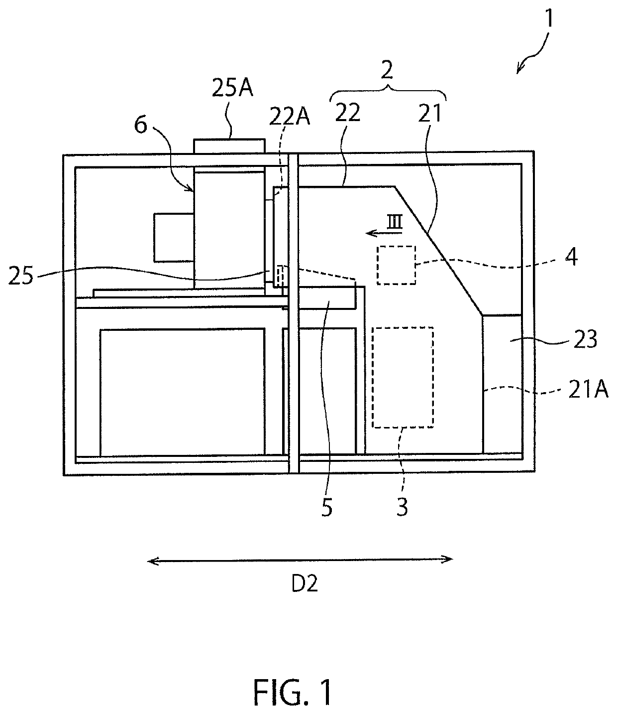
[0040]FIG. 1 is a side view of an air conditioner 1 according to an embodiment of the present invention. As shown in FIG. 1, the air conditioner 1 according to the embodiment comprises an air flow path 2 through which air flows, a cooler 3, a heating unit 4 and a humidifier 5, which are disposed in the air flow path 2, and a blower 6 that creates a driving force for allowing air to flow through the air flow path 2. The air flow path 2 has a vertical channel 21 that extends vertically, and a horizontal channel 22 that communicates with an upper part of the vertical channel 21 and extends horizontally from the upper part. In the below description, a direction orthogonal to a sheet plane of FIG. 1 along the horizontal direction is referred to as “first direction D1”, and a direction orthogonal to the first direction D1 along the ...


PUM

PropertyMeasurementUnit
angleaaaaaaaaaa
lengthaaaaaaaaaa
photosensitiveaaaaaaaaaa

Abstract

An air conditioner including; an air flow path through which air flows; a plate having an air through hole installed in a downstream opening of the air flow path; and a humidifier disposed on the air flow path and capable of supplying vapor into the air flow path. The air flow path has a horizontal channel provided with the downstream opening and extending along a horizontal direction, and the humidifier is disposed on the horizontal channel. The humidifier includes a water storage tank opened upward to an inside of the horizontal channel, and a heater that heats the water in the storage tank. The air conditioner further includes a moisture absorption member that extends in an up and down direction, above a wall part of the storage tank on the side of the plate, or diagonally thereabove on the side of the plate.

Description

BACKGROUND OF THE INVENTIONField of the Invention[0001]The present invention relates to an air conditioner.Description of Related Art[0002]In a pattern forming step in the manufacture of a semiconductor, a photolithography is sometimes utilized. In the photolithography, a photosensitive resist is applied to a substrate, and then the resist is exposed to light corresponding to a desired pattern. When the resist is a photo-curing type photosensitive material, for example, an area of the resist, which is not exposed to light, is removed by a solvent. Thus, the desired pattern can be formed (developed) on the resist.[0003]It is known that a film thickness of such a resist applied or exposure may change, depending on a temperature and a humidity. Thus, when a temperature and a humidity of air in an environment surrounding the resist largely differ from a desired temperature and a humidity, dimensional precision of a formed pattern may be significantly lowered. Thus, in general, a tempera...

Claims


Application Information

Patent Timeline
Patent Type & Authority Patents(United States)
IPC IPC(8): F24F6/02F24F6/08G03F7/20
CPCF24F6/025F24F6/08G03F7/70858F24F2006/008F24F6/043H01L21/67017
Inventor SASAKI, ISAMU
Owner SHINWA CONTROLS
Why Eureka
Try Eureka