Air conditioner

Active Publication Date: 2020-02-13
SHINWA CONTROLS
View PDF0 Cites 1 Cited by
  • Summary
  • Abstract
  • Description
  • Claims
  • Application Information

AI Technical Summary

Problems solved by technology

However, the present inventor has found that a humidity spike is likely

Method used


Image

  • Air conditioner
  • Air conditioner
  • Air conditioner

Examples


Embodiment Construction

[0038]An embodiment of the present invention is described in detail below, with reference to the attached drawings.

[0039](Overall Structure of Air Conditioner)

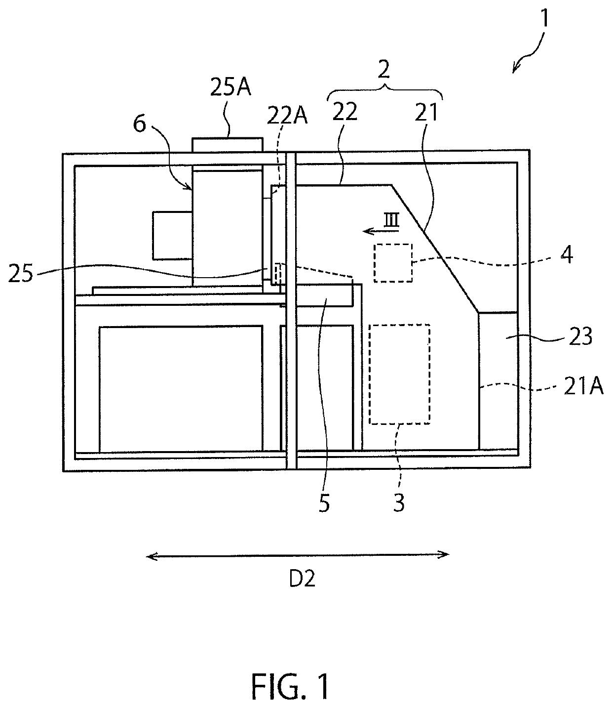
[0040]FIG. 1 is a side view of an air conditioner 1 according to an embodiment of the present invention. As shown in FIG. 1, the air conditioner 1 according to the embodiment comprises an air flow path 2 through which air flows, a cooler 3, a heating unit 4 and a humidifier 5, which are disposed in the air flow path 2, and a blower 6 that creates a driving force for allowing air to flow through the air flow path 2. The air flow path 2 has a vertical channel 21 that extends vertically, and a horizontal channel 22 that communicates with an upper part of the vertical channel 21 and extends horizontally from the upper part. In the below description, a direction orthogonal to a sheet plane of FIG. 1 along the horizontal direction is referred to as “first direction D1”, and a direction orthogonal to the first direction D1 along the ...


PUM


Abstract

An air conditioner including; an air flow path through which air flows; a plate having an air through hole installed in a downstream opening of the air flow path; and a humidifier disposed on the air flow path and capable of supplying vapor into the air flow path. The air flow path has a horizontal channel provided with the downstream opening and extending along a horizontal direction, and the humidifier is disposed on the horizontal channel. The humidifier includes a water storage tank opened upward to an inside of the horizontal channel, and a heater that heats the water in the storage tank. The air conditioner further includes a moisture absorption member that extends in an up and down direction, above a wall part of the storage tank on the side of the plate, or diagonally thereabove on the side of the plate.

Description

TECHNICAL FIELD[0001]The present invention relates to an air conditioner.BACKGROUND ART[0002]In a pattern forming step in the manufacture of a semiconductor, a photolithography is sometimes utilized. In the photolithography, a photosensitive resist is applied to a substrate, and then the resist is exposed to light corresponding to a desired pattern. When the resist is a photo-curing type photosensitive material, for example, an area of the resist, which is not exposed to light, is removed by a solvent. Thus, the desired pattern can be formed (developed) on the resist.[0003]It is known that a film thickness of such a resist applied or exposure may change, depending on a temperature and a humidity. Thus, when a temperature and a humidity of air in an environment surrounding the resist largely differ from a desired temperature and a humidity, dimensional precision of a formed pattern may be significantly lowered. Thus, in general, a temperature and a humidity of an apparatus for perfor...

Claims


Application Information

Patent Timeline
IPC IPC(8): F24F6/02F24F6/08
CPCF24F6/025F24F6/08G03F7/70858F24F2006/008F24F6/043H01L21/67017
Inventor SASAKI, ISAMU
Owner SHINWA CONTROLS
Why Eureka
Try Eureka